ELECTRICAL
673831-Rev A 4-53
4
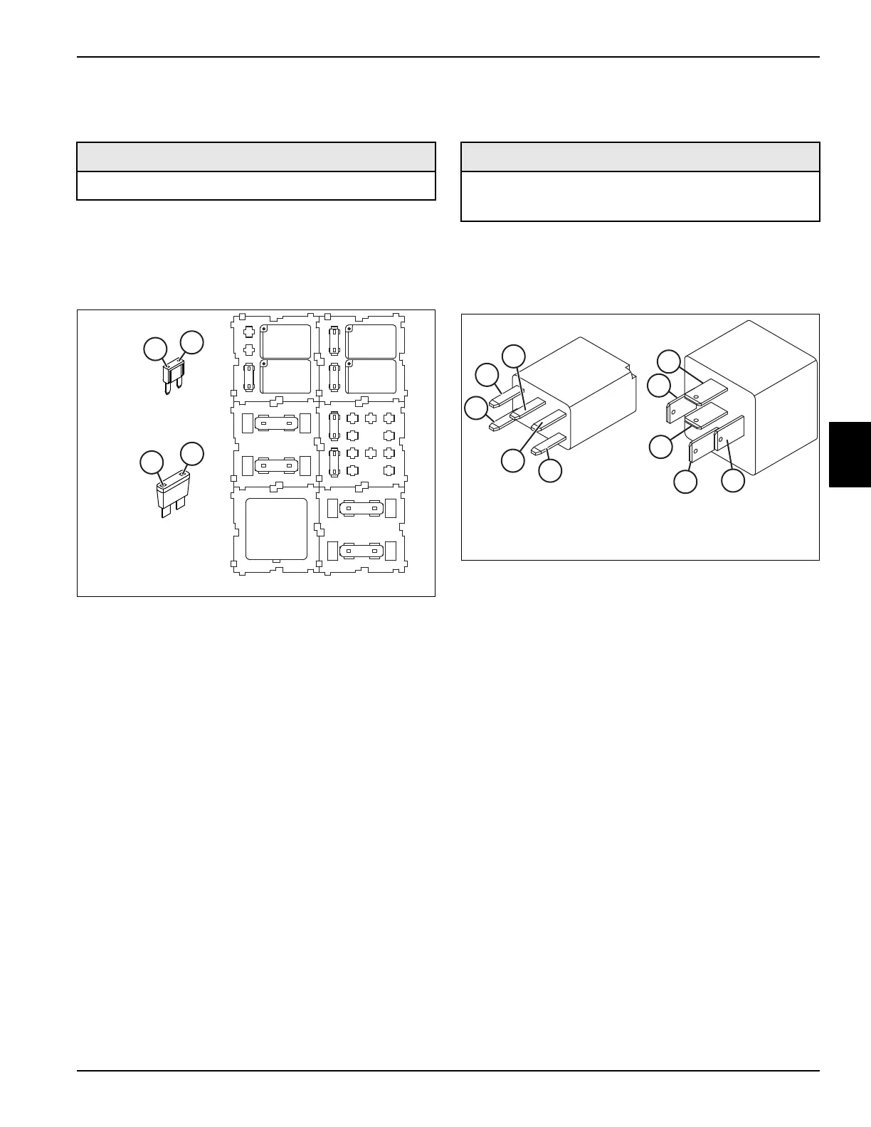
Fuse Test
See Figure 4-23.
1. Park the mower safely. (See “Park Mower Safely” on
page 1-6.)
2. Identify the fuse in the fuse block. It is not necessary
to remove the fuse for testing.
Figure 4-23
3. Small openings are provided at the top of the fuse for
testing. Connect test leads to terminals (1 and 2).
4. Check for continuity.
Is continuity indicated?
YES Fuse is good.
NO Fuse is faulty; replace fuse.
Relays Test
See Figure 4-24.
1. Park the mower safely. (See “Park Mower Safely” on
page 1-6.)
2. Remove relay. (See “Relays” on page 4-65.)
Figure 4-24
3. Connect one test lead to terminal (1).
4. Connect the other test lead to terminal (3) and check
for continuity.
Is continuity indicated?
YES Proceed to step 5.
NO The relay is faulty; replace the relay.
5. Connect one test lead to terminal (1).
6. Connect the other test lead to terminal (4).
7. Connect a 12-volt DC power source to terminals (2
and 5).
8. Check for continuity across terminals (4 and 1).
Is continuity indicated?
YES The relay is good.
NO The relay is faulty; replace the relay.
Required Tools or Equipment
Digital Multimeter, Ohmmeter, or Continuity Tester
10
30
Mini Fuse
F1, F4, F6, F7, F8
ATO Fuse
F2, F3, F5, F9
1
2
1
2
K1
F10
K3
15 20
F7
F4
K4
10
F1
K5
20 10
F8
F6
30
F3
K2
30
F5
40
F2
30
F9
Required Tools or Equipment
• Digital Multimeter, Ohmmeter, or Continuity Tester
• 12-volt DC Power Source
1
2
3
5
4
1
2
3
5
4
35-amp Micro Relay
K1, K3, K4, K5
40-amp Relay
K2

 Loading...

