HYDRAULICS
673831-Rev A 6-55
6
Assembly Notes
• Assemble the lift valve by reversing the order of
disassembly.
• Use a new seal kits during assembly.
• Lubricate all O-rings prior to assembly.
• After assembling four bolts (8), completely cover bolt
holes on top of solenoid valve (3) with silicone
sealant.
• Tighten plugs (5) to 11 lb–ft (15 N·m).
• Tighten gauge port plug (9) to 17 lb-ft (23 N·m).
• Tighten coil nuts (6) to 10 lb-ft (13.5 N·m).
• Tighten relief valve (1) to 24–26 lb-ft (32.5–35.3
N·m).
• Tighten check valves (2) to 19–21 lb-ft (25.8–28.5
N·m).
Reel Valves
Rear Reel Valve
Removal and Installation
See Figure 6-59.
1. Park the mower safely. (See “Park Mower Safely” on
page 1-6.)
2. Remove the operator’s platform.
3. Drain hydraulic oil tank. (See “Hydraulic Oil Tank—
Drain Procedure” on page 6-49.)
4. Thoroughly clean the valve, especially the area
surrounding the hydraulic hoses, tubes, and fittings.
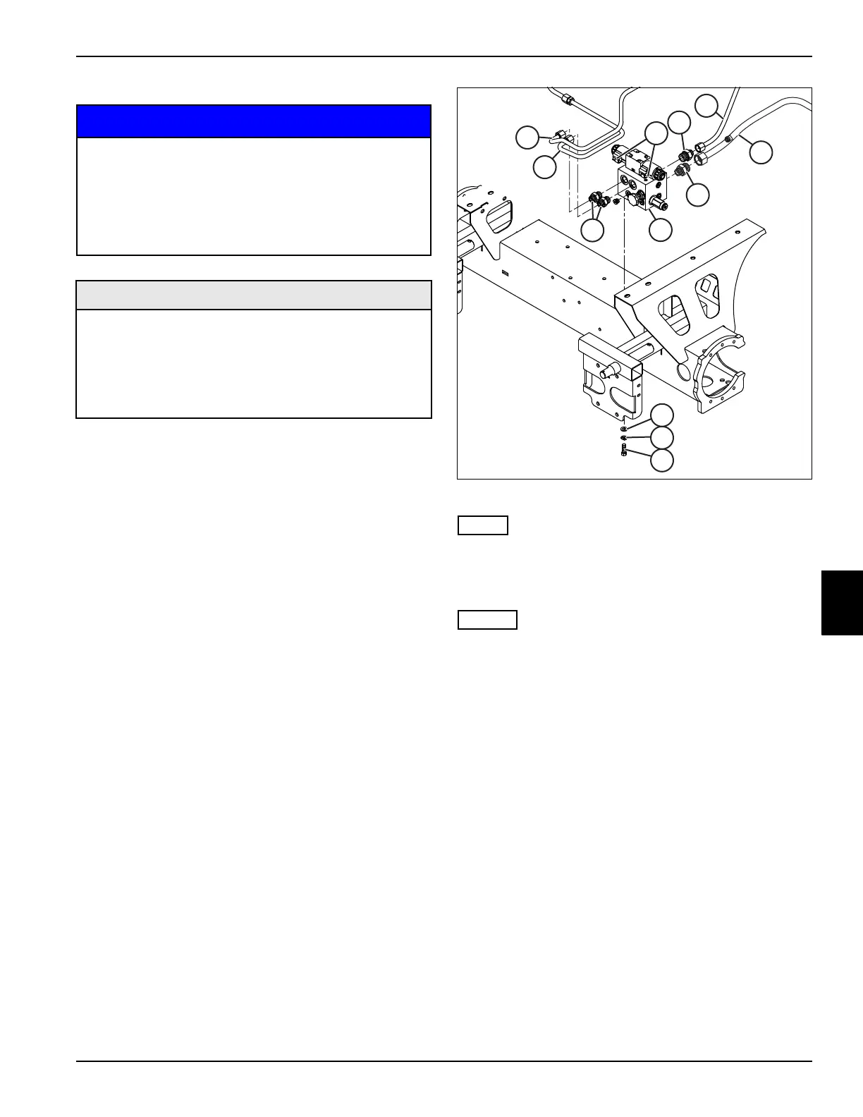
Figure 6-59
Label connectors before disconnecting to ensure correct
installation.
5. Disconnect electrical connectors (1) from solenoid.
• Label all hydraulic hoses and tubes before
disconnecting to aid in installation.
• Close all openings with caps or plugs to prevent
contamination.
6. Disconnect rear reel tubes (2 and 3).
7. Remove two straight fittings (4).
8. Disconnect the charge pressure tube (5).
9. Remove straight fitting (6).
10. Disconnect pressure tube (7).
11. Remove straight fitting (8).
12. Remove mounting screws (9), lock washers (10) and
flat washers (11).
13. Remove the rear reel valve (12).
It is important that all component parts are
absolutely clean, as contamination can result in
serious damage and/or improper operation.
Never use shop towels or rags to dry parts after
cleaning, as lint may clog passages. Dry parts
using compressed air.
Required Materials
• Solenoid Valve O-Rings (Jacobsen P/N 339908 -
Qty 4)
• Relief Valve Seal Kit (Jacobsen P/N 5003579)
• Check Valve Seal Kit (Jacobsen P/N 5003578)
• Silicone Sealant (Jacobsen P/N 3004694)

 Loading...

