ELECTRICAL
673831-Rev A 4-67
4
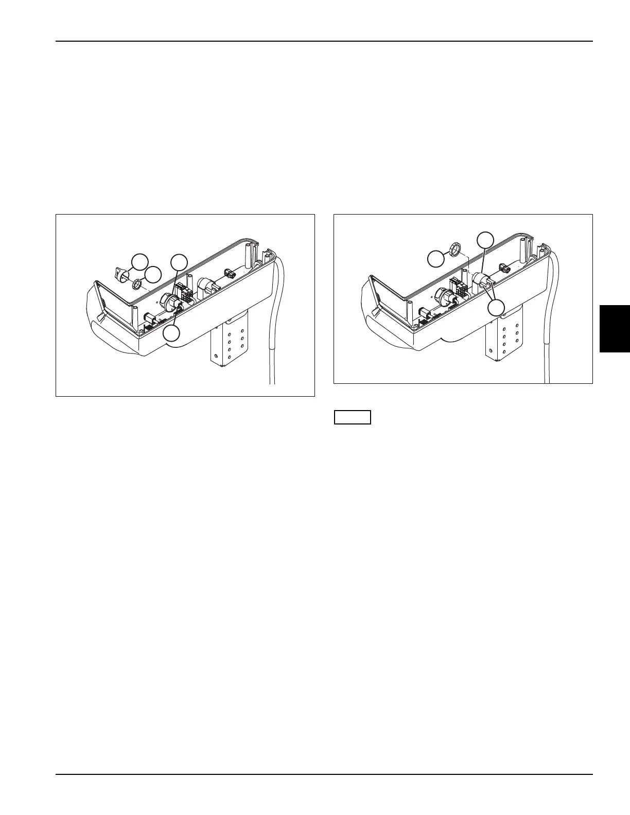
Key Switch
Removal and Installation
See Figure 4-47.
1. Park the mower safely. (See “Park Mower Safely” on
page 1-6.)
2. Disconnect the negative (–) battery cable at the
battery.
3. Remove instrument panel. (See “Instrument Panel”
on page 4-64.)
Figure 4-47
Label all wires before disconnecting to ensure correct
installation.
4. Remove six pin harness connector (1) from the key
switch (2).
5. Remove key (3) from the key switch (2).
6. Remove face nut (4) from the key switch (2).
7. Remove the key switch (2).
Installation Note
• Adjust backing nut for proper switch height, if
necessary.
• Install the key switch by reversing the order of
removal.
LDU Buzzer
Removal and Installation
See Figure 4-48.
1. Park the mower safely. (See “Park Mower Safely” on
page 1-6.)
2. Disconnect the battery negative (–) cable at the
battery.
3. Remove instrument panel. (See “Instrument Panel”
on page 4-64.)
Figure 4-48
Label all wires before disconnecting to ensure correct
installation.
4. Disconnect wire terminals (1).
5. Remove ring nut (2).
6. Remove LDU buzzer (3).
Installation Notes
Install LDU buzzer by reversing the order of removal.

 Loading...

