ACCESSORIES AND MISCELLANEOUS REPAIR
673831-Rev A 9-11
9
Rear Wheels
Removal and Installation
See Figure 9-12.
1. Park the mower safely. (See “Park Mower Safely” on
page 1-6.)
Figure 9-12
3WD rear wheel shown. 4WD rear wheels similar.
2. Loosen, but do not remove, five wheel-to-hub
spherical nuts (1).
3. Raise and support rear of machine with jack stands.
4. Remove five wheel-to-hub spherical nuts (1).
5. Remove wheel (2) and inspect tire for tears or other
damage.
6. Replace tire if damage is excessive.
Installation Notes
• Inspect and clean any rust from hub (3) or wheel
mounting area. Apply anti-seize compound to
wheel-to-hub spherical nuts (1).
• Install wheel by reversing the order of removal.
• Tighten wheel-to-hub spherical nuts to 85–90 lb-ft
(115–120 N·m) using an alternating pattern.
• Set tire pressure to 16 psi (1.1 bar).
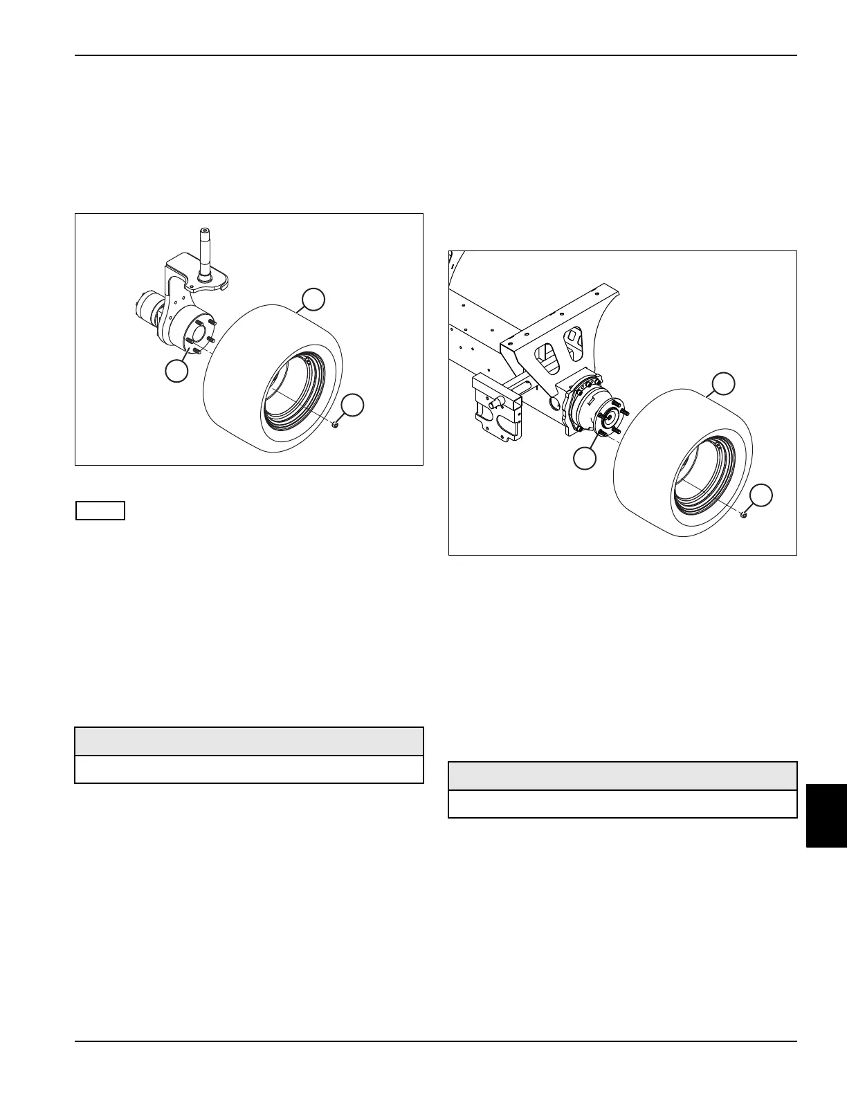
Front Wheels
Removal and Installation
See Figure 9-13.
1. Park the mower safely. (See “Park Mower Safely” on
page 1-6.)
2. Block both sides of rear wheels using suitable wheel
blocks.
Figure 9-13
3. Loosen, but do not remove, five wheel-to-hub
spherical nuts (3).
4. Raise and support front of machine with jack stands.
5. Remove five wheel-to-hub spherical nuts (3).
6. Remove wheel (2) and inspect tire for tears or other
damage.
7. Replace tire if damage is excessive.
Installation Notes
• Inspect and clean any rust from hub (1) or wheel
mounting area. Apply anti-seize compound to
wheel-to-hub spherical nuts (3).
• Install wheel by reversing the order of removal.
• Tighten wheel-to-hub spherical nuts to 85–90 lb-ft
(115–120 N·m) using an alternating pattern.
• Set tire pressure to 16 psi (1.1 bar).
Required Materials
Anti-Seize Compound
Required Materials
Anti-Seize Compound

 Loading...

