4-66 673831-Rev A
ELECTRICAL
4
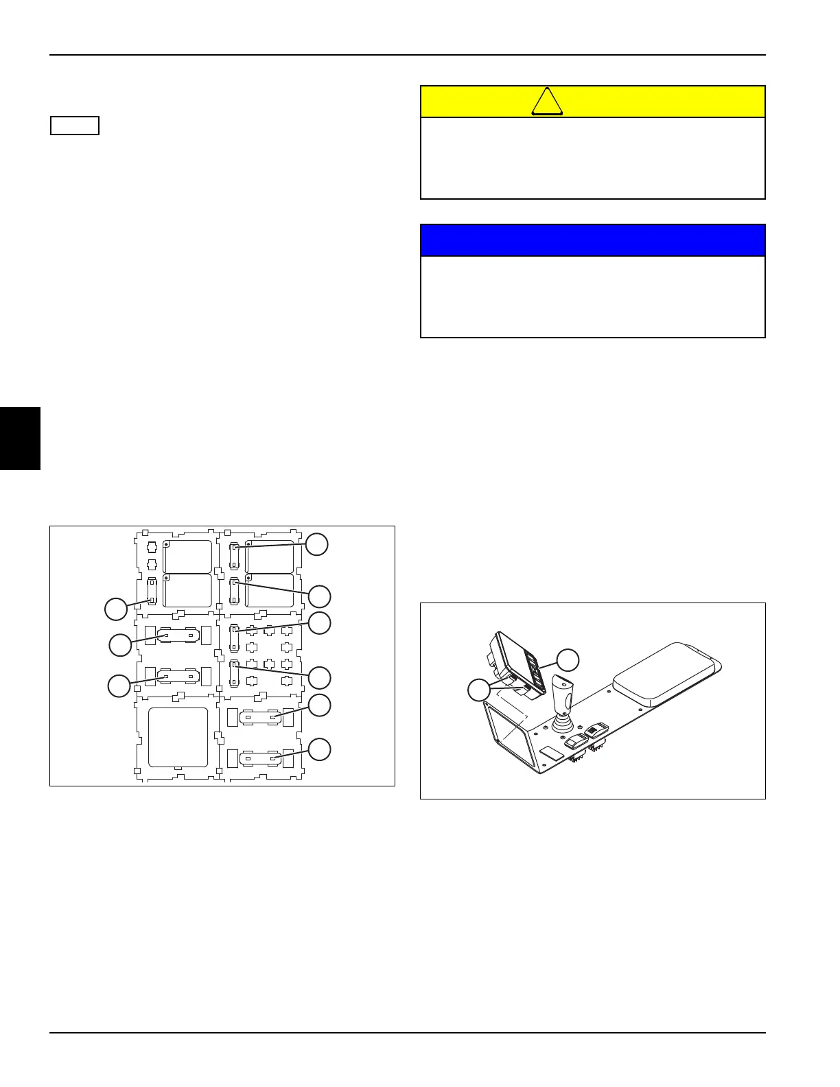
Fuses
This procedure applies to the following relays:
• 10-amp accessory outlet fuse F1 (1)
• 40-amp glow plug fuse F2 (2)
• 30-amp ignition relay fuse F3 (3)
• 15-amp key switch/LDU fuse F4 (4)
• 30-amp fan fuse F5 (5)
• 20-amp MCU fuse F6 (6)
• 20-amp MCU fuse 2 F7 (7)
• 10-amp air ride seat/fan relay fuse F8 (8)
• 30-amp starter relay fuse F9 (9)
Removal and Installation
See Figure 4-45.
1. Park the mower safely. (See “Park Mower Safely” on
page 1-6.)
2. Disconnect the negative (–) battery cable at the
battery.
3. Remove the rear access panel on the operator
platform.
Figure 4-45
4. Identify the fuse to be removed. Pull the fuse straight
out of the relay base.
Installation Note
Install the fuse by reversing the order of removal.
LDU
Removal and Installation
See Figure 4-46.
1. Park the mower safely. (See “Park Mower Safely” on
page 1-6.)
2. Disconnect the negative (–) battery cable at the
battery.
3. Remove the instrument panel.
Figure 4-46
4. Disconnect 12 pin harness connector from the LDU.
5. Press tabs (1) on both sides of the LDU (2) and
remove the LDU from the instrument panel.
Installation Note
Install the LDU by reversing the order of removal.
K1
F10
K3
15 20
F7
F4
K4
10
F1
K5
20 10
F8
F6
30
F5
K2
30
F3
40
F2
30
F9
1
2
3
4
5
6
7
8
9
To prevent injury to the operator or damage to the
mower, never replace a fuse with a higher
amperage rating fuse.
Never bypass fuses. Fire damage may result.
For proper operation of the SLF530 mower, do
not insert a fuse in the F10 location.
Placing a fuse in the F10 location will select the
wrong program in the mower controller.
1
2

 Loading...

