9-8 673831-Rev A
ACCESSORIES AND MISCELLANEOUS REPAIR
9
Armrest
Removal and Installation
See Figure 9-7.
1. Park the mower safely. (See “Park Mower Safely” on
page 1-6.)
2. Remove instrument panel. (See “Instrument Panel”
on page 4-64.)
Figure 9-7
3. Remove two screws (1) and cover (2).
4. Tag and disconnect armrest harness from mower
harness.
5. Support the armrest (6).
6. Remove three screws (3), washers (4) and flange
nuts (5).
7. Lift armrest assembly off the mower.
Installation Notes
Install the armrest by reversing the order of removal.
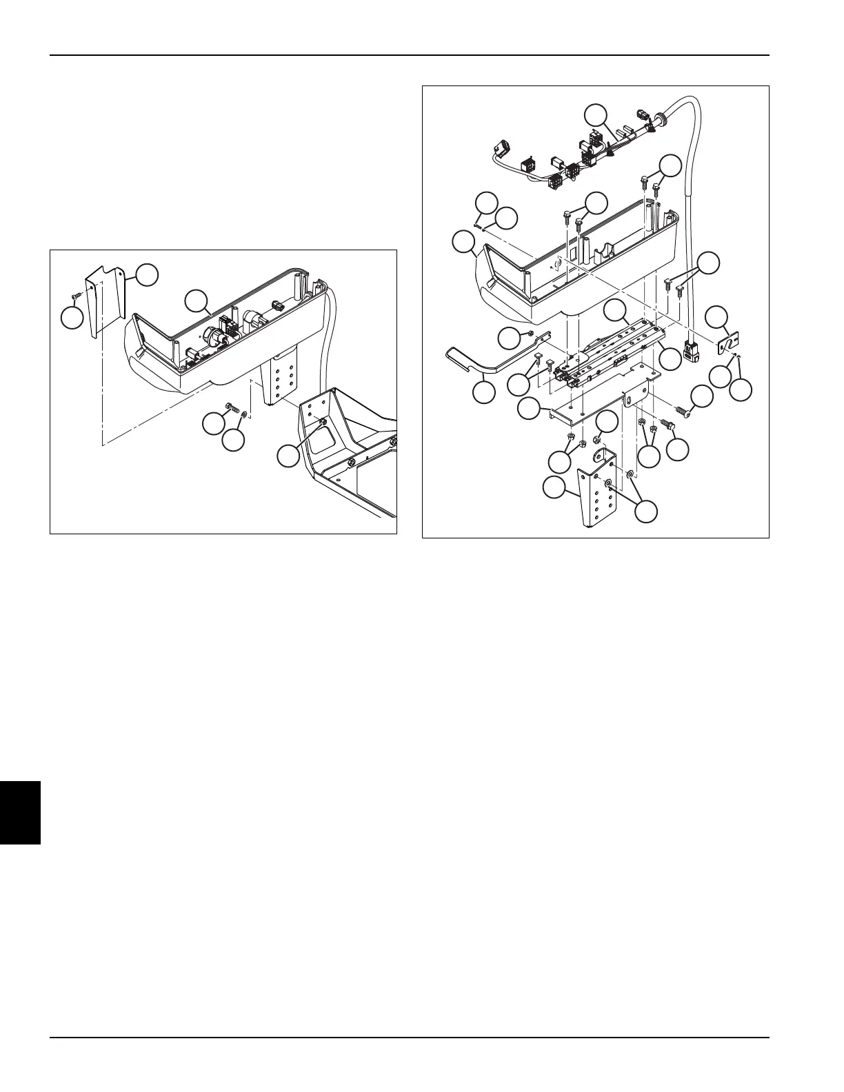
Disassembly and Assembly
See Figure 9-8.
1. Remove key switch. (See “Key Switch” on
page 4-67.)
2. Remove light switch. (See “Rocker Switches” on
page 4-64.)
3. Remove LDU buzzer. (See “LDU Buzzer” on
page 4-67.)
Figure 9-8
1. Remove two screws (1), four washers (2), two nuts
(3) and switch plate (4).
2. Remove four screws (9), harness (11) and armrest
housing (12).
3. Remove nut (18) and adjuster handle (19).
4. Remove four screws (13) and nuts (14). Lift latching
rail (17) and sliding rail (16) off armrest plate (15).
5. Remove screw (5), screw (20), washers (6), nut (7)
and armrest mount (8).
Assembly Notes
Assemble armrest in reverse order of disassembly.
If replacing latching rail (17), remove handle that comes
with the rail and assemble handle (19).
1
2
2
3
4
5
6
7
8
9
20
9
11
12
13
13
14
14
15
16
17
18
19

 Loading...

