ELECTRICAL
673831-Rev A 4-65
4
5. Press the wings (6) on the front and back of the
switch. Remove the switch from the panel.
Installation Note
Install the rocker switches by reversing the order of
removal.
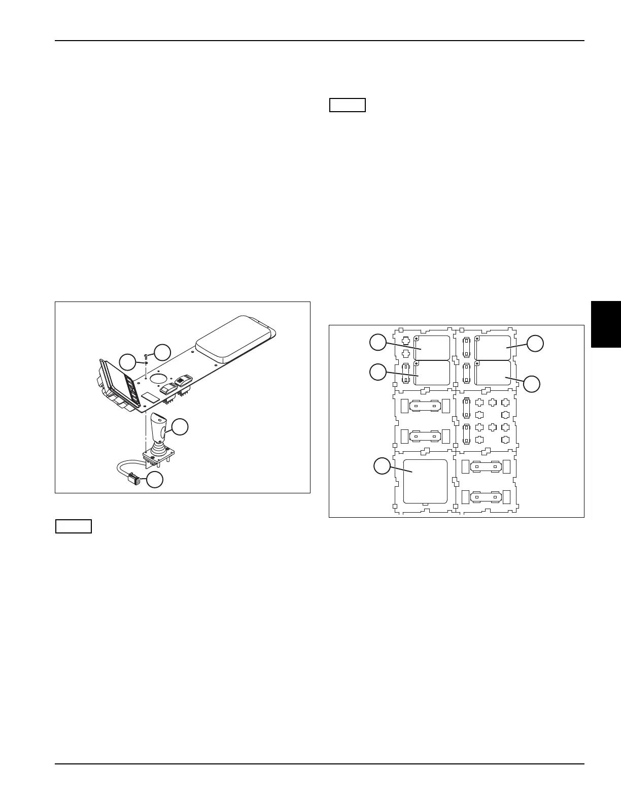
Lift/Lower Joystick
Removal and Installation
See Figure 4-43..
1. Park the mower safely. (See “Park Mower Safely” on
page 1-6.)
2. Disconnect the negative (–) battery cable at the
battery.
3. Remove the instrument panel. (See “Instrument
Panel” on page 4-64.)
Figure 4-43
Label all wires before disconnecting to ensure correct
installation.
4. Disconnect the six pin connector (1) from the mower
harness.
5. Remove four screws (2) and flat washers (3).
6. Remove the lift/lower joystick (4).
Installation Note
Install joystick by reversing the order of removal.
Relays
See Figure 4-44.
This procedure applies to the following relays:
• Ignition Relay (1)
• Glow Plug Relay (2)
• Starter Relay (3)
• Fan Relay (4)
• 4WD Relay (5)
Removal and Installation
1. Park the mower safely. (See “Park Mower Safely” on
page 1-6.)
2. Disconnect the negative (–) battery cable at the
battery.
3. Remove the rear access panel on the operator
platform.
Figure 4-44
4. Identify the relay to be removed. Pull the relay
straight out of the relay base.
Installation Note
Install the relay by reversing the order of removal.
K1
F10
K3
15 20
F7
F4
K4
10
F1
K5
20 10
F8
F6
30
F5
K2
30
F3
40
F2
30
F9
1
2
3
4
5

 Loading...

