5-58 673831-Rev A
HYDROSTATIC POWER TRAIN
5
32. Apply Loctite
®
638 retaining compound to the
external diameter of bushing (22), and position
bushing on valving cover (18) with the chamfer of the
bushing facing toward the valving cover.
33. Using the large diameter end of brake shaft (25) and
a soft-faced hammer, install bushing (22) into valving
cover flush to 0.004 in. (0.1 mm) below surface.
34. Remove excess retaining compound from each side
of bushing.
35. Install new O-ring (23) and new backup ring (24).
36. Install brake shaft (25).
37. Apply Mobilux EP2 grease, or equivalent NLGI
Grade EP2 grease, to the brake housing (38) brake
shaft grooves and brake O-ring contact surface, and
to the top of the brake piston (32), spring washer
(36), and snap ring (35).
When removing retaining compound residue from
valving cover (18) or brake housing (38), do not file or
emery the surface. The original surface finish must
be maintained.
38. Ensure any dried retaining compound on the brake
housing mating surfaces of valving cover (18) and
brake housing (38) is removed. Scrape off all
retaining compound residue with a blade.
After degreasing with isopropyl alcohol, do not touch
the mating surfaces of the valving cover and brake
housing with hands or fingers.
39. Clean/degrease the brake housing mating surfaces
of valving cover (18) and brake housing (38) with
isopropyl alcohol.
• After applying activator, do not touch the brake
housing mating surface of the valving cover.
• Do not apply any activator on the brake shaft.
40. Apply a film of Loctite
®
7471 activator on the brake
housing mating surface of the valving cover (18), and
wait 2 minutes before continuing procedure. Do not
apply any activator on brake shaft (25).
41. Install new O-ring (21) in valving cover.
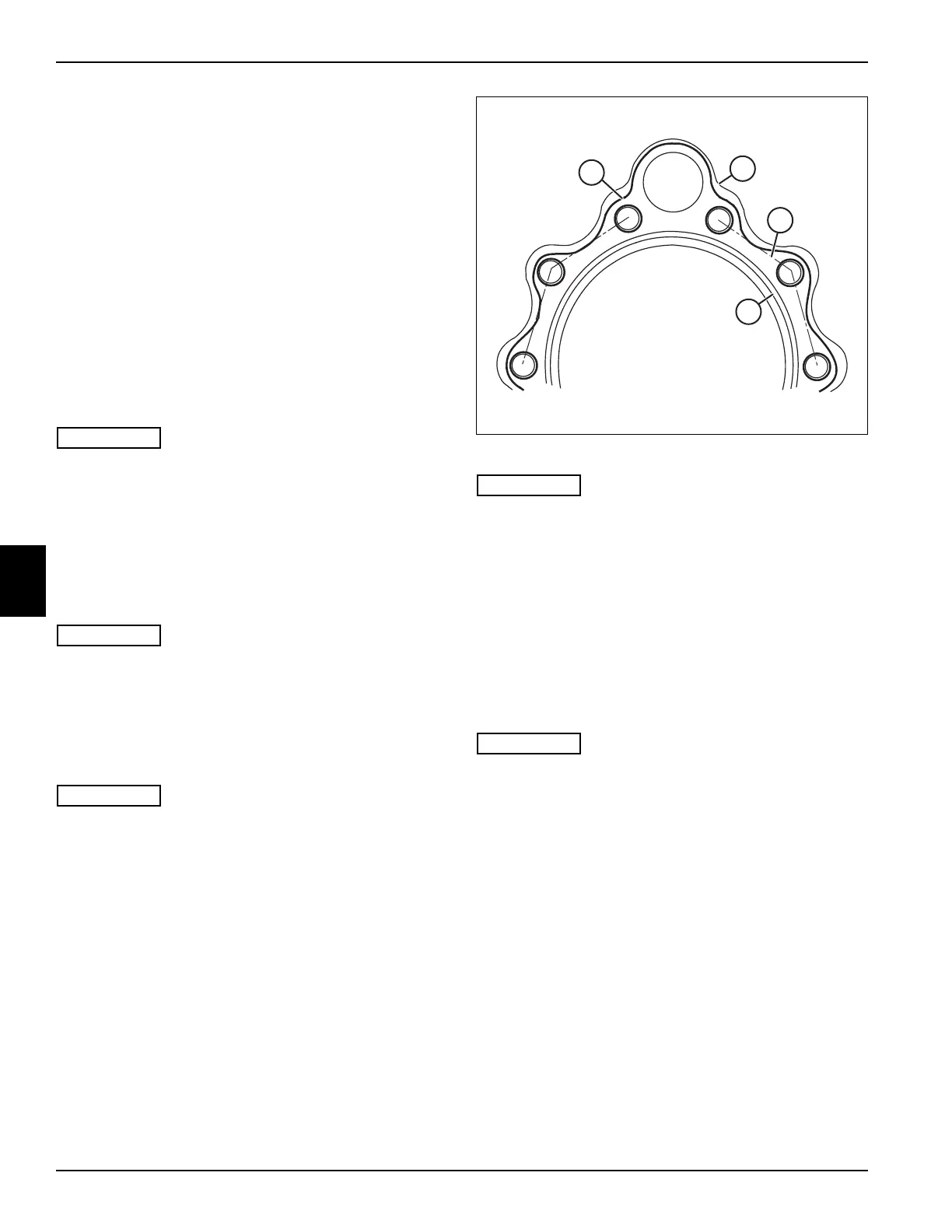
Figure 5-63
• When placing bead of Loctite® 638 retaining
compound on valving cover, make sure no
retaining compound is placed on the O-ring
groove (51).
• Step 43 must be completed within 10 minutes of
applying Loctite® 638 retaining compound in
step 42.
42. Place a 0.2–0.4 in. (5–10 mm) wide continuous bead
(no gaps) of Loctite
®
638 retaining compound (49) on
valving cover (18), following the median line (50) of
the mounting screw hole centers.
The glued connection remains fragile up to six hours
after being glued. During this time, avoid any shock
to the glued parts; do not use or test the brake or the
wheel motor.
43. Place brake housing onto valving cover and install
ten screws (37). Tighten screws to 107 ± 10% lb-ft
(145 ± 10% N·m) in an alternating pattern.

 Loading...

