HYDROSTATIC POWER TRAIN
673831-Rev A 5-67
5
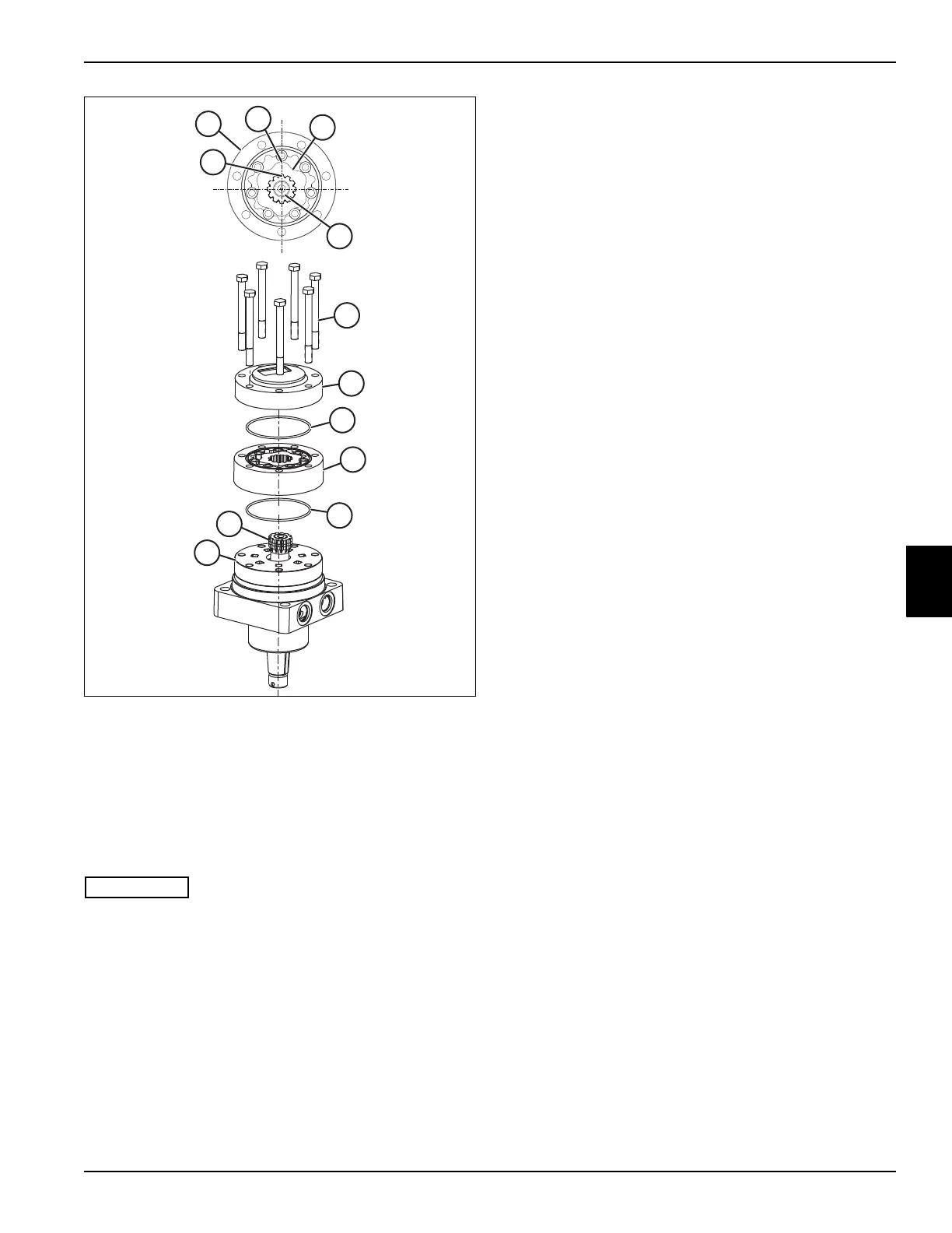
Figure 5-81
16. Grease two O-rings (6) and assemble to geroler
assembly (22).
17. Assemble the geroler assembly (22) to the valve
plate (21) with the splined end away from the
housing. For proper timing, the marked spline (Y) of
the drive (12) must be aligned with a geroler star tip
(W).
If marked spline (Y) of drive (12) aligns with a geroler star
valley (V), the motor timing will not be correct and the
motor will rotate in the wrong direction.
18. Assemble the end cap (23) to the geroler assembly
(24).
19. Assemble seven hex head screws (24). Tighten
screws to 37–47 lb-ft (51–61 N·m).

 Loading...

