8-34 673831-Rev A
CUTTING UNITS
8
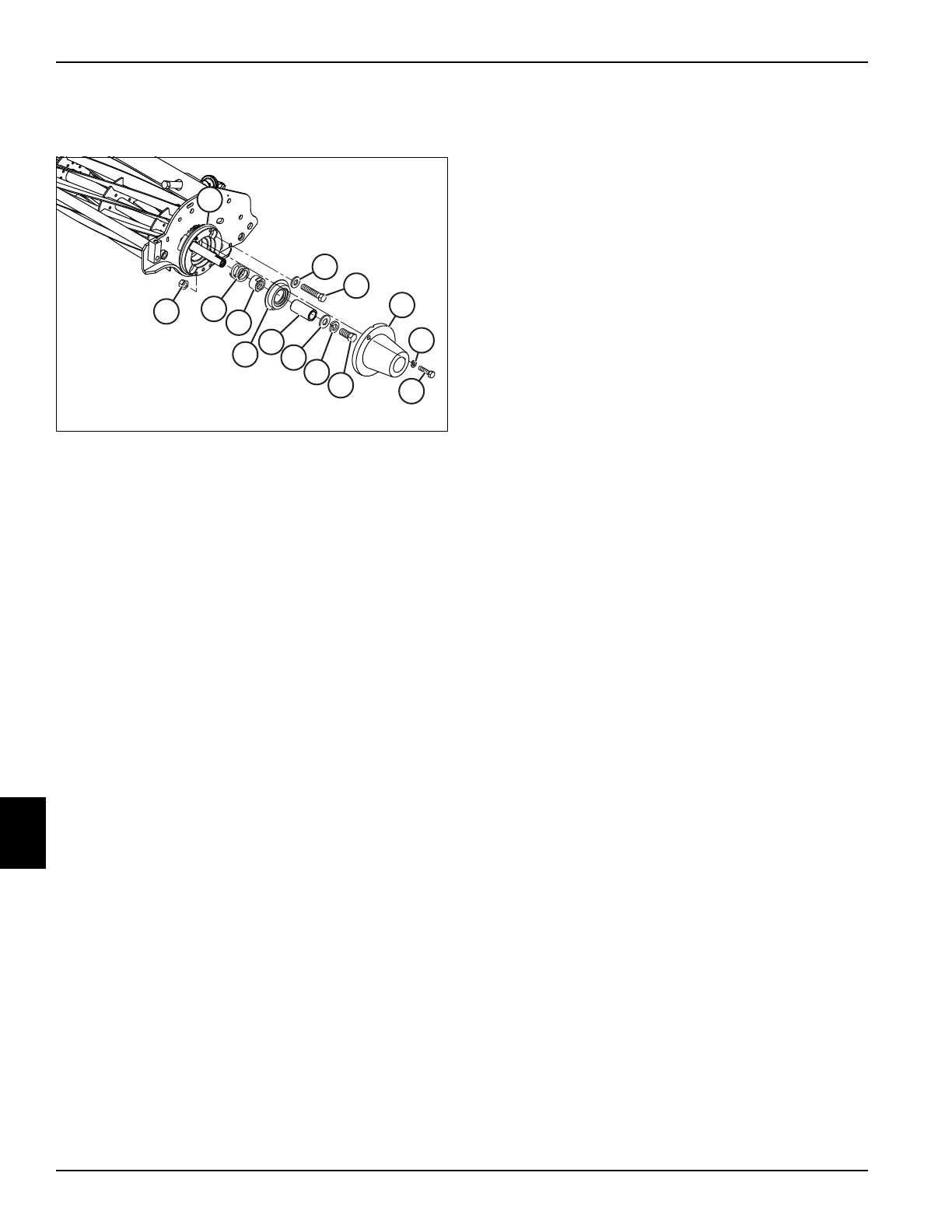
Installation—Non-Drive Side
See Figure 8-30.
Figure 8-30
1. Install reel bearing housing assembly (15).
2. Install spring (13) and nut (12).
3. Tighten adjuster nut (12) until the spring (13) is
completely collapsed and the bearing is seated on
the shaft, then back the nut out 2–3 turns, or until
there is 0.040 in. (1.0 mm) side-to-side movement of
the reel.
4. Install seal (11) using mounting screws (8), washers
(9), and nuts (10).
5. Tighten mounting screws (8) to 18–22 lb-ft (24.4–
29.8 N·m).
6. Lubricate grease fitting with grease that meets or
exceeds NLGI Grade 2 LB specifications. Clean
grease fitting before lubricating and apply grease to
the fitting with a hand grease gun only. Pump the gun
slowly until a slight amount of pressure is felt, then
stop—do not overgrease. Do not use an
air-powered grease gun.
7. Install spacer (7), washer (6), lock washer (5), and
screw (4).
8. Adjust bedknife-to-reel clearance. (See
“Height-of-Cut (HOC) Adjustment” on page 8-19.)
9. Install counterweight (3), two screws (1), and two
washers (2).
10. Install grass shield. (See “Grass Shield” on
page 8-27.)
11. Install cutting unit front roller. (See “Front Roller” on
page 8-36.)
12. Install cutting unit to mower. (See “Cutting Unit” on
page 8-22.)

 Loading...

