8-6
Electrical System
4st 2/2.5/3.5 2007
3) Inspection of Igniter
1. Remove igniter, and turn plug cap counterclockwise to
remove it from high tension cord.
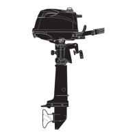
2. Measure igniter resistance. Replace if other than specified
value.
Remove the part and test it as a separate unit.
Use of analog tester is suitable for checking the
polarity. The instrument HIOKI3030 indicates a
resistance ranging from 5 to 9kΩ. A digital tester
may indicate reversed polarity and resistance
ranging from 2 to 6MΩ.
Igniter Resistance (at 20˚C) :
Secondary Coil:Between High Tension Cord and
Black (B)
2.0 - 3.0 kΩ
Secondary Coil:Between Plug Cap and Black (B)
5.5 - 9.5 kΩ
Igniter Diode Polarity (at 20˚C):
Primary Circuit:Between Black (B) and Brown (Br)
No conduction
Primary Circuit:Between Brown (Br) and Black (B)
Conductive
3. Install plug cap onto high tension cord by twisting clockwise.
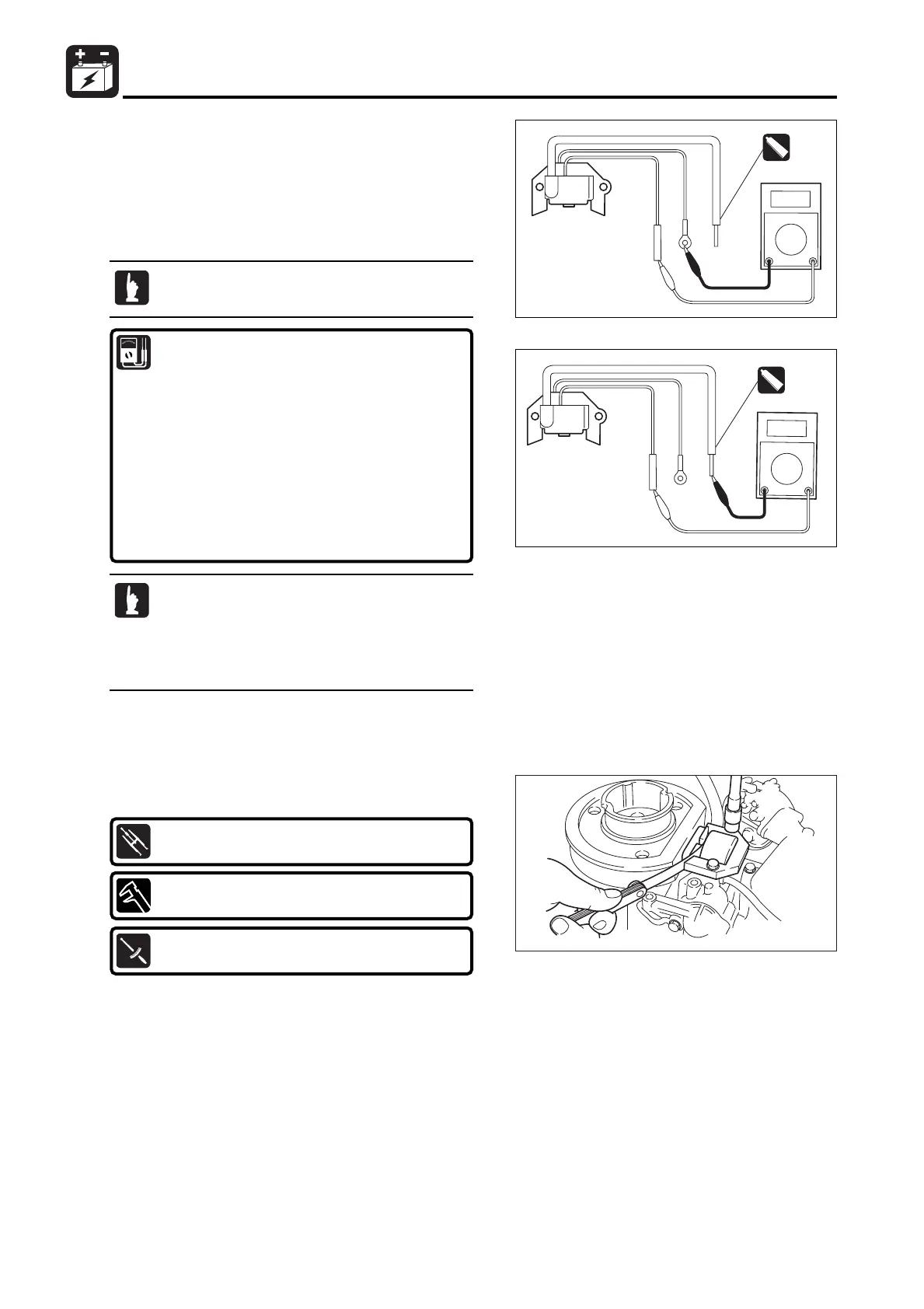
4. Install igniter so that specified clearance is achieved, and
connect plug cap to spark plug.
5. Connect igniter lead to stop switch.
Igniter Clearance:
0.2 - 0.4mm(0.008 - 0.016in)
Igniter Bolts:
6 N · m (4 lb · ft) [0.6 kgf · m]
Thickness Gauge 1:
P/N. 353-72251-0
MFS2sec08070524.qxd07.5.243:22 PM ページ6
 Loading...