5
5-27
4st 2/2.5/3.5 2007
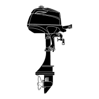
Connecting Rod Bolts :
1st
tightening torque : 5 N · m (4 lb · ft) [0.5 kgf · m]
2nd tightening torque : 10 N · m (7 lb · ft) [1.0 kgf · m]
6. Tighten connecting rod bolts 7 in two steps to specified
torque.
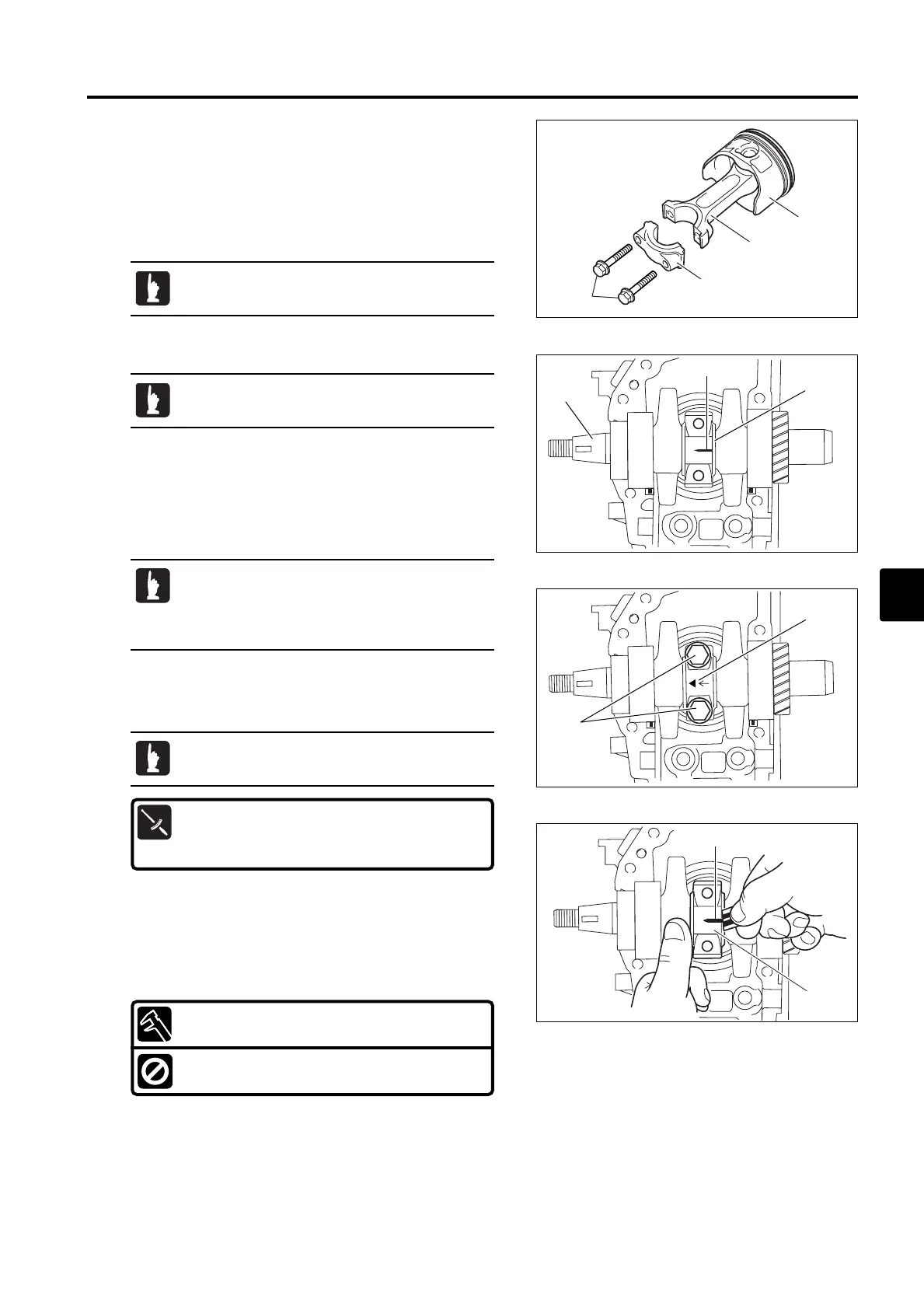
28) Inspection of Crank Pin Oil Clearance
1. Clean crank shaft 1 and connecting rod parts 2 and 3.
2. Place cylinder block upside down on the work bench.
Install piston 4 to connecting rod 2, and then, install the
assembly to cylinder block.
3. Install crank shaft 1 to cylinder block.
4. Place a commercially available plasti-gauge 5 on the
crank pin 6 so that is parallel to crank shaft 1.
5. Install connecting rod 2 and cap 3 to crank pin 6.
1
5
6
Do not move connecting rod and crankshaft until
oil clearance measurement is completed.
· Be sure to install the cap 3 in original position
(direction).
· Be sure that connecting rod "▲ " mark a
points crank shaft flywheel side.
7. Remove connecting rod cap 3 and measure width of
crushed plasti-gauge 5 on the crank pin 6. Replace
connecting rod 2 or crank shaft 1 if the measurement
(converted value) is over the limit.
Big End Oil Clearance : Converted value
0.015 - 0.041 mm (0.00059 - 0.00161 in)
Functional Limit :
0.060 mm (0.00236 in)
Do not attach piston rings in this step.
When installing, bring projection of bearing to notch
of cylinder block.
MFS2sec05070524.qxd07.5.243:18 PM ページ27
 Loading...