5-40
Power Unit
4st 2/2.5/3.5 2007
Pivot Lock Nut
10 N · m (7 lb · ft) [1.0 kgf · m]
2. Install push rod plate 3 and tighten pivot bolt 4 to
specified torque.
3. Attach push rod 5, rocker arm 6 and pivot 7, and then,
attach pivot lock nut 8.
4. Adjust valve clearance.
a
2
6
7
8
5
3
4
4st OIL
4st
OIL
5. Tighten pivot lock num 8 to specified torque.
Do not turn flywheel while the locker arm is
free. Doing so can make push rod and
rocker arm interfere with each other,
resulting in damages to these parts.
Perform adjustment of valve clearances when
engine is cold.
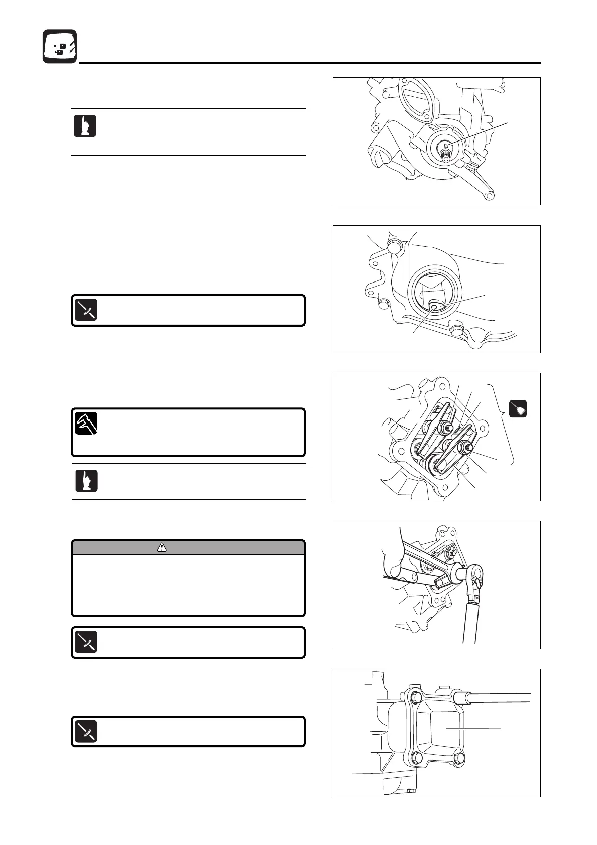
Set piston to top dead center of compression
stroke. Remove oil filler cap and check that ø5mm
(0.2 in) hole a of cam shaft gear 2 can be seen.
39) Assembly of Rocker Arm
1. Direct magneto key groove 1 to piston top dead center.
6. Install cylinder head cover 9 and tighten to specified
torque.
Cylinder Head Cover Bolts :
6 N · m (4 lb · ft) [0.6kgf · m]
Valve Clearance (when engine is cold)
IN : 0.06 - 0.14 mm(0.0024 - 0.0055 in)
EX : 0.11 - 0.19 mm(0.0043 - 0.0075 in)
Pivot Bolt :
25 N · m (18 lb · ft) [2.5 kgf · m]
MFS2sec05070524.qxd07.5.243:18 PM ページ40
 Loading...