6
6-35
4st 25/30 2022
Proper Backlash Obtained from Gauge Reading:
0.60 - 0.64 mm (0.0236 - 0.0252 in)
Sizes of Adjusting Shims:
For Bevel Gear B Side: 0.1, 0.15, 0.3, 0.5 mm
Backlash Measuring Tool Kit:
P/N. 3C8-72234-2
Measuring Tool Set Piece 3:
P/N. 346-72245-1
Backlash Measuring Tool Clamp 9:
P/N. 3B7-72720-0
Dial Gauge Plate 8:
P/N. 3B7-72729-0
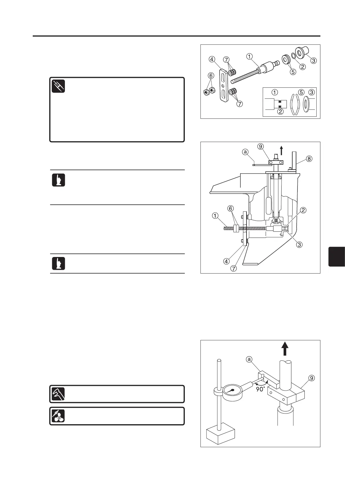
2. Install the backlash measuring tool kit 1 to 7 and tighten
with the bolts.
3. Install the dial gauge plate 8 with the bolts and washers.
4. Put two nuts (M10) 6 on the screw-side rear end of the
shaft 1, and screw the nuts onto the shaft with a wrench.
When the drive shaft starts to rotate as the nuts are
turned, screw the nuts an additional 45 degrees. Secure
the shaft in this state.
5. Secure the clamp 9 to the drive shaft with a bolt. Preload
the bearing by turning the drive shaft several times while
pulling it up in the direction shown by the arrow to give it
a good fit. Use a dial gauge to read the backlash at the
notch location.
33)
Backlash Measurement Between Bevel
Gear Assy A and Bevel Gear B and Shim
Selection
1 Shaft
2 O-ring
3 Collar
4 Plate
5 Cone Disk Spring
6 Nut x 2
7 Washer x 6
Measure the backlash between the bevel gear
assy A and the bevel gear B with the propeller
shaft housing, propeller shaft, and reverse (C)
gear removed from the gear case.
Use commercially available bolts (M6) and
washers (t = 4.5 mm).
1. Install the pump case (lower) following the procedure in
Chapter 6, “Assembly of Lower Unit."
 Loading...