8-22
Electrical System
4st 25/30 2022
6) Adjustment of the Pulser Coil Air Gap
1. Loosen the mounting screws of the pulser coil 1 and
insert the thickness gauge into the gap a between the
pulser coil and the encoder ring 3 on the flywheel 2.
Pulser Coil Air Gap: a
0.6 to 1.0 mm (0.024 to 0.039 in)
2. Tighten the mounting screws of the pulser coil.
The gap between the encoder ring and the pulser
coil can be kept even by tightening the screws
while pushing the pulser coil lightly toward the
flywheel.
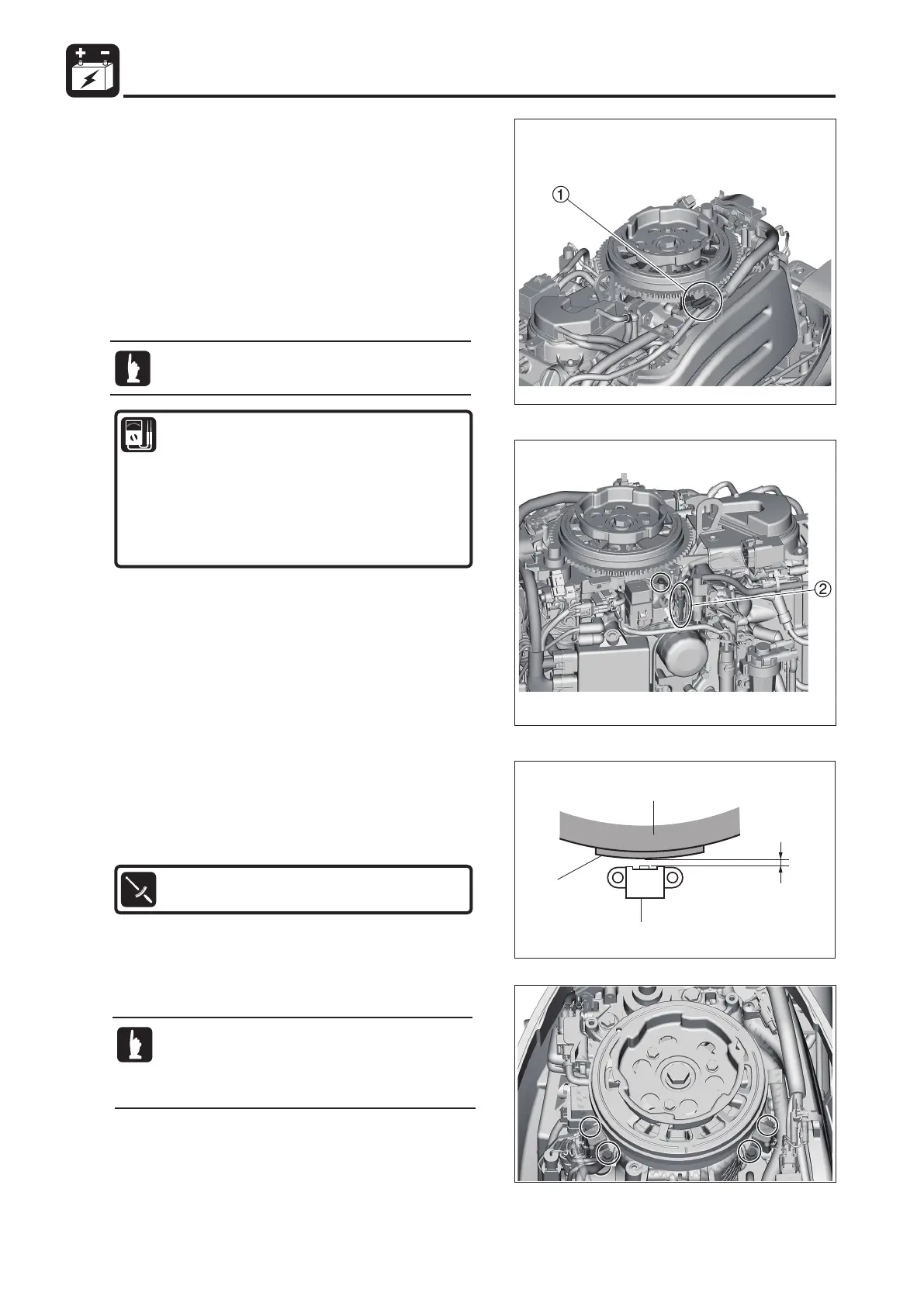
5) Inspection of the Pulser Coils
1. Disconnect the #1 pulser coil connector 1 on the
starboard side.
2. Measure the resistance of the #1 pulser coil. Replace it if
the value is not as specified.
3. Disconnect the #2 pulser coil coupler 2 (1 pin) on the port
side and test the #2 pulser coil in the same way as #1.
Pulser Coil Resistance
(Reference Value): #1
Between Red (R) and Black (B) terminals
WRїDW&
(Reference Value): #2
Between Red/Yellow (R/Y) and Block Ground.
WRїDWʝ
1 #1 Pulser coil (1 pin)
2 #2 Pulser coil (1 pin)
This test can be conducted without removing the
part.

 Loading...