Fuel System (Fuel Injection)
4-22
4st 25/30 2022
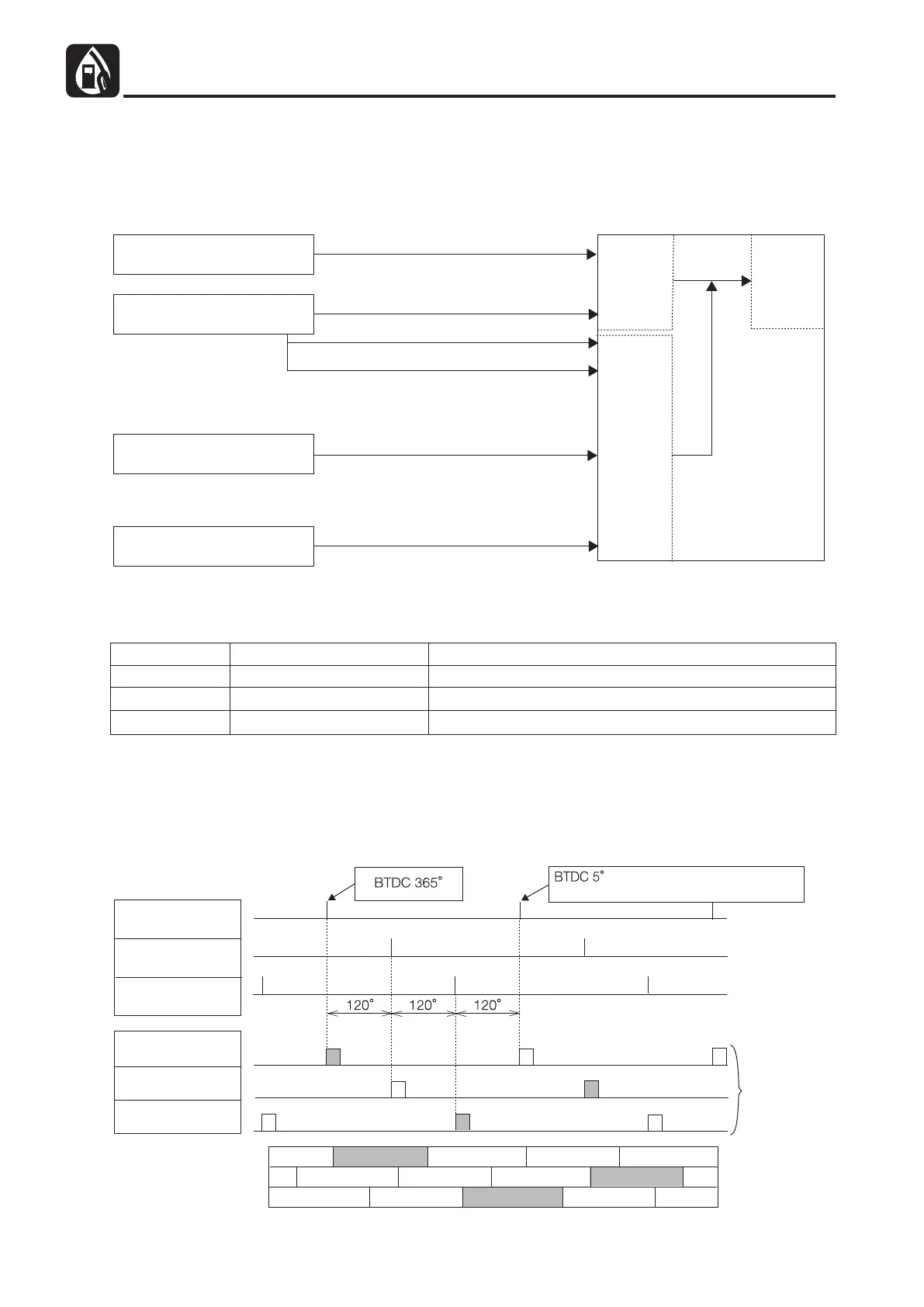
(3) Fuel Injection Control
The ECU calculates the intake air quantity based on the engine revolution speed and intake manifold pressure
(intake vacuum pressure) to determine the fuel injection amount.
During engine startup, warm-up, acceleration/deceleration, and idling, the ECU performs correction control based on
information from the sensors.
Pulser Coil
T-MAP (Manifold Pressure,
Manifold Temperature) Sensor
Engine Temperature Sensor
TPS (Throttle Position) Sensor
Engine Revolution Speed and Crank Angle
Manifold Pressure (Intake Vacuum Pressure)
Atmospheric Pressure at Starting
Manifold Intake Air Temperature
Change of Pressure (Vacuum Pressure)
at Acceleration/Deceleration
Cylinder Cooling Water Temperature
Injection
Amount
Correction
Basic
Injection
Amount
ECU
1) Fuel Injection Timing
Fuel injection timing at starting and during normal operation are described in the following table.
Cylinder No.
1
2
3
Reference Signal
#1 Crank Angle Signal
#2 Crank Angle Signal
#3 Crank Angle Signal
Injection Timing (with reference to individual cylinders)
BTDC 365° and BTDC 5°
BTDC 365° and BTDC 5°
BTDC 365° and BTDC 5°
Remarks: 1) No. of fuel injections : Once per revolution of each cylinder (around the end of the compression and
exhaust strokes)
2) Injection sequence : #1 ¤ #2 ¤ #3 ¤ #1 ¤ #2 ¤ #3 ¤ #1 (for every 120° of the crank angle)
3) Combustion sequence : #1 ¤ #3 ¤ #2 ¤ #1 (for every 240° of the crank angle)
4) Injection timing diagram is shown below.
Crank Angle Signal
of No. 1 Cylinder
Crank Angle Signal
of No. 2 Cylinder
Crank Angle Signal
of No. 3 Cylinder
Injector of No. 1
Cylinder
Injector of No. 2
Cylinder
Injector of No. 3
Cylinder
Strokes of No. 1 Cylinder
Strokes of No. 2 Cylinder
Strokes of No. 3 Cylinder
(with reference to No. 1 cylinder
compression stroke top dead center)
Exhaust
Injection
Timing
CombustionCompressionIntakeExhaust
ExhaustCombustionCompression Intake
Compression
ExhaustCombustion Intake Compression Combustion
Injection Timing Diagram
 Loading...