8-32
Electrical System
4st 25/30 2022
Charge Coil Resistance: Reference Value (at 20°C)
Between Yellow (Y) terminal and Yellow (Y) or
Green (G) terminal
WRї
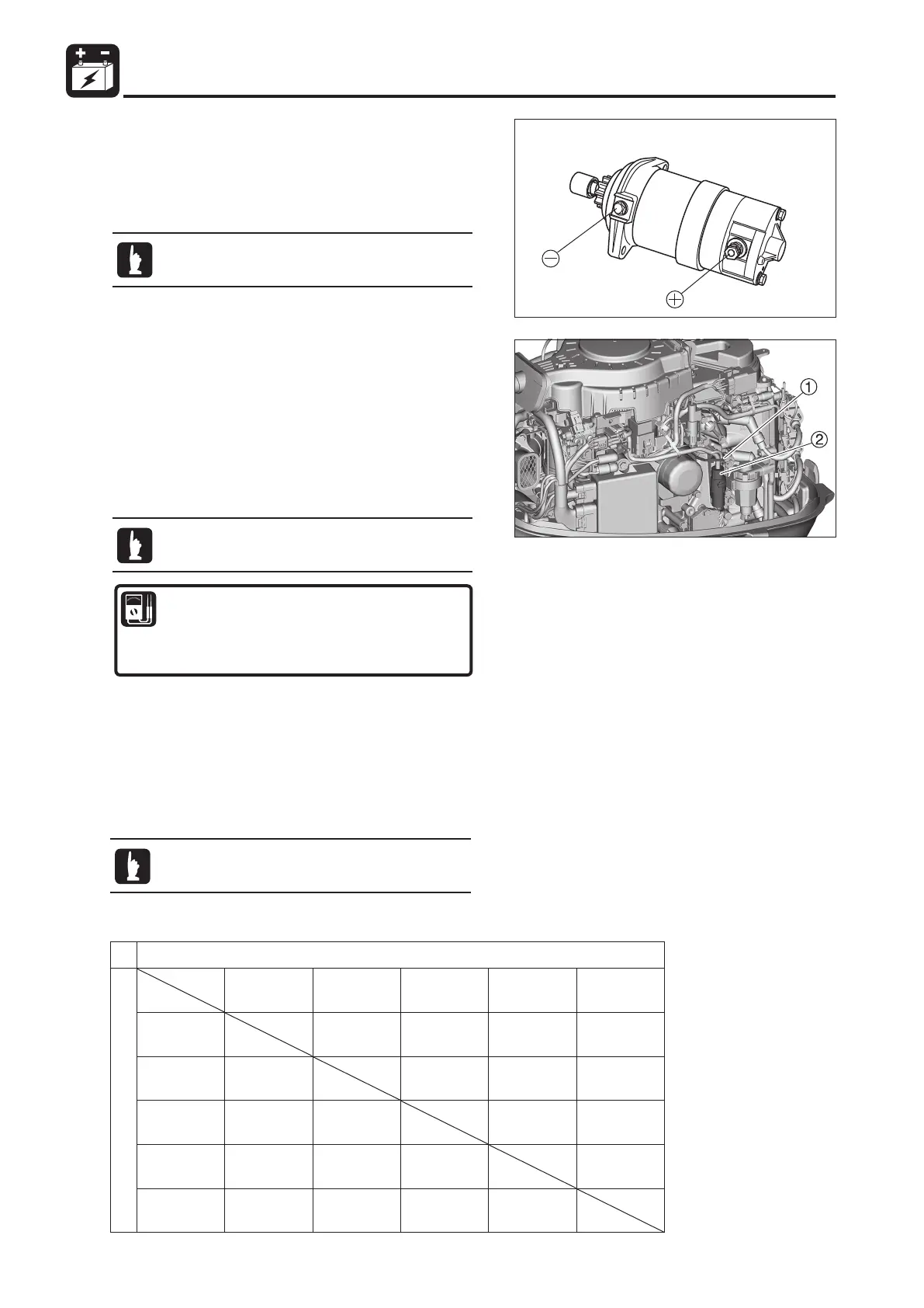
7. The Charging System
(Except for MF)
1) Inspection of the Charge Coil
1. Remove the wire band 1 on the cable from the charge
coil, located on the rectifier.
2. Disconnect the charge coil cable connector 2 and
measure the resistance
.
This test can be conducted without removing the
part.
2) Inspection of the Rectifier
&KHFN WKHZLUHKDUQHVVIRUDQ\GLVFRQQHFWLRQVRU
problems with the terminal connection.
&KHFNWKHFRQGXFWLYLW\RI HDFKSDUWDFFRUGLQJ WRWKH
following table. The values in ( ) are reference values.
'LVFRQQHFW DOO FRQQHFWLRQV DQG PHDVXUH DV D VHSDUDWH
unit.
Rectifier Tester Check Table
This test can be conducted without removing the
part.
"ON" means conductive, and "OFF" means not conductive.
7) Starter Motor Operation Test
1. Assemble the starter motor and, before and after installing
it in the power unit, apply an electric current between the
positive and negative points to confirm that it is working
normally.
Be careful of fire, because the operating test
generates sparks.
Positive tester lead wire
Negative tester lead wire
White (W) Black (B) Yellow (Y) Yellow (Y) Yellow (Y)
White (W) OFF OFF OFF OFF
Black (B)
ON
Nї
ON
Nї
ON
Nї
ON
Nї
Yellow (Y)
ON
Nї
ON
Nї
ON
Nї
ON
Nї
Yellow (Y)
ON
Nї
ON
Nї
ON
Nї
ON
Nї
Yellow (Y)
ON
Nї
ON
Nї
ON
Nї
ON
Nї

 Loading...