AssemblingtheFrontSteeringAssembly
g037253
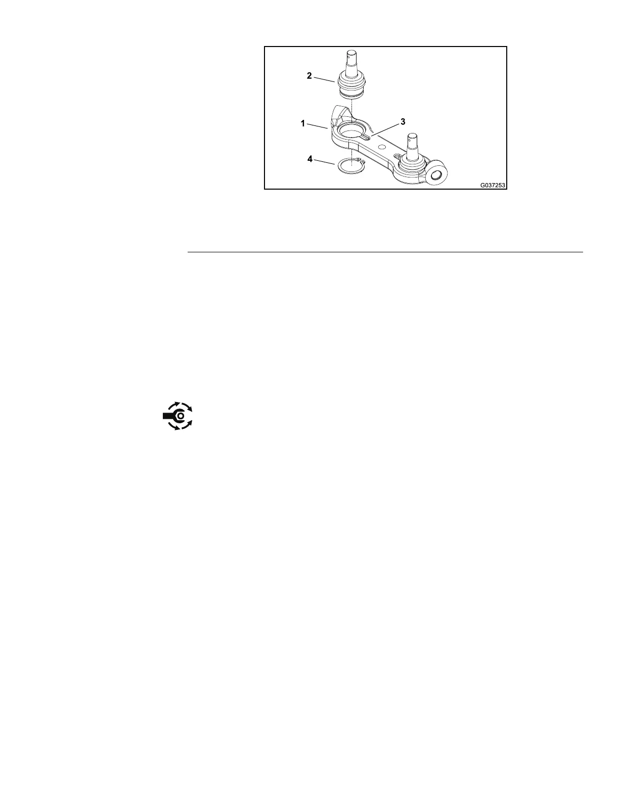
Figure276
1.Centerlink3.Centerlinknotch
2.Balljoint4.Retainingring
1.Installallthefrontsteeringcomponentsthatwereremoved(Figure274).
NotethetorquespecicationsidentiedinFigure274duringassembly.Ifthe
frontaxlewasremovedfromtheframe,usethewashers(item36inFigure
274)sothattheaxlehaslessthan0.76mm(0.030inch)freeplaybetween
theframeandaxlesupport.Iftheballjointswereremovedfromthecenter
link,pressnewballjointsintothecenterlinkfromthesideofthelinkthathas
anotchattheballjointbore(Figure276).
2.Installthetierod(item31inFigure274)tothemachineasfollows:
A.Ifthetierodassemblyisbeingreplaced,adjustthenewtierodassembly
totheapproximatelengthoftheremovedtierod.
B.ApplyLoctite#271(orequivalent)tothethreadsoftheinnertierodend.
Threadthetierodintothecenterlinkandtorqueto95to108N∙m(70
to80ft-lb).
C.Cleanthetapersofthesteeringforkandballjointstudoftheoutertie
rodend.
D.Inserttheoutertierodendballjointstudintothesteeringforkand
securewiththeslottedhexnut.T orquetheslottedhexnutto48to54
N∙m(35to40ft-lb).Ifnecessary,tightentheslottedhexnutfurther
untiltheslotinthenutalignswiththeholeinthetierodballjointstud.
Installthecotterpin.
3.Ifthesteeringcylinderwasremoved,installthesteeringcylinder;referto
InstallingtheSteeringCylinder(page4–151).
4.Ifthefrontsteeringforkassemblywasremoved,installthesteeringfork;refer
toInstallingtheFrontSteeringFork(page6–29).
5.Ifthefrontwheelmotorwasremoved,installthewheelmotor;referto
InstallingtheFrontWheelMotor(page4–85).
6.Ifthefrontwheelwasremoved,installthewheel;refertoInstallingtheWheel
(page6–14).
7.Installthefrontcovertothefrontaxle(Figure275).
Groundsmaster360
Page6–33
Chassis:ServiceandRepairs
16225SLRevC

 Loading...


