Encompass 4 Reader System Guide
4-32
2. Connect the red wire (CTS) from the yellow and red wire pair to pin 7 of the DB9
con
nector or pin 4 of the DB25 connector.
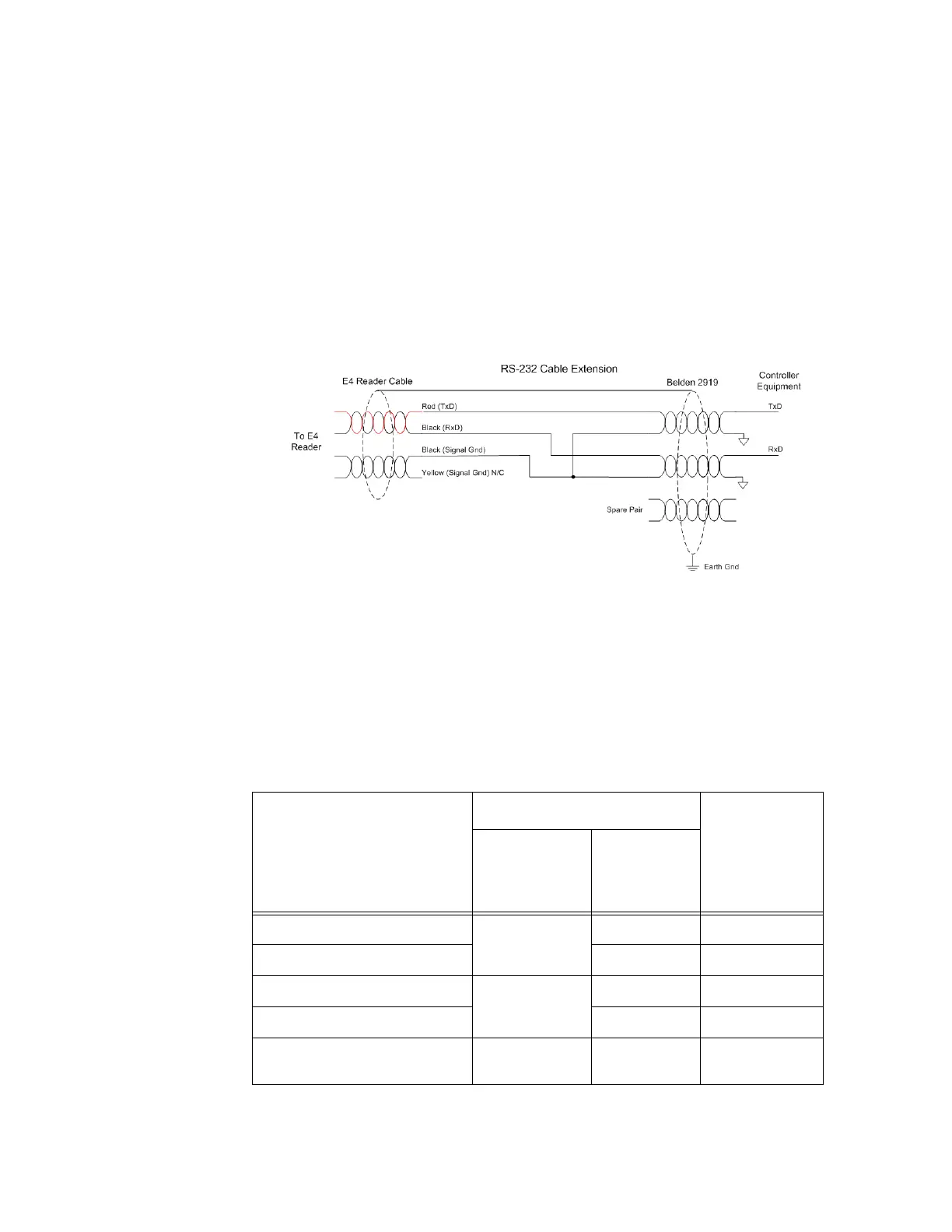
Note: When extending the RS-232 interface, us
e a three-pair cable such as Belden
2919. Use a twisted pair for the Black (RxD) with ground (Black of the Black and Yel-
low pair), and a twisted pair for Red (TxD) with ground (Black of the Black and Yel-
low pair). The third pair of the three-pair cable
can be used for a spare in the event
either of the other two pair are damaged or fail. The cable shield should be tied to a
single-point Earth Ground on the controller end of the cable Refer to Figure 4-21.
Figure 4-21 RS-232 Cable Extension Diagram
RS–422 Interface
RS–422 interface signals are supplied by four wires from the Encompass 4 Reader
communications cable. Your host must have an RS
–422 interface with either an inter-
nal or external converter.
Table 4-7 shows the RS
–422 signals and their interface wires.
Table 4-7 RS–422 Interface Signal Wiring for Colored-Wire Pair Cable
Signal from Encompass 4
Read
er
Colored-Wire Pair Cable
Connect to
Sign
al from
Host
Wire Pair
fr
om
Encompass 4
Reader
Color Used
RS
–422 Transmit positive Yellow/Red Yellow Receive (+)
RS
–422 Transmit negative Red Receive (–)
RS
–422 Receive positive Red/Black Black Transmit (+)
RS
–422 Receive negative Red Transmit (–)
Signal Ground Yellow/Black Yellow or
Black
Signal Ground