Wiring Tables
C-5
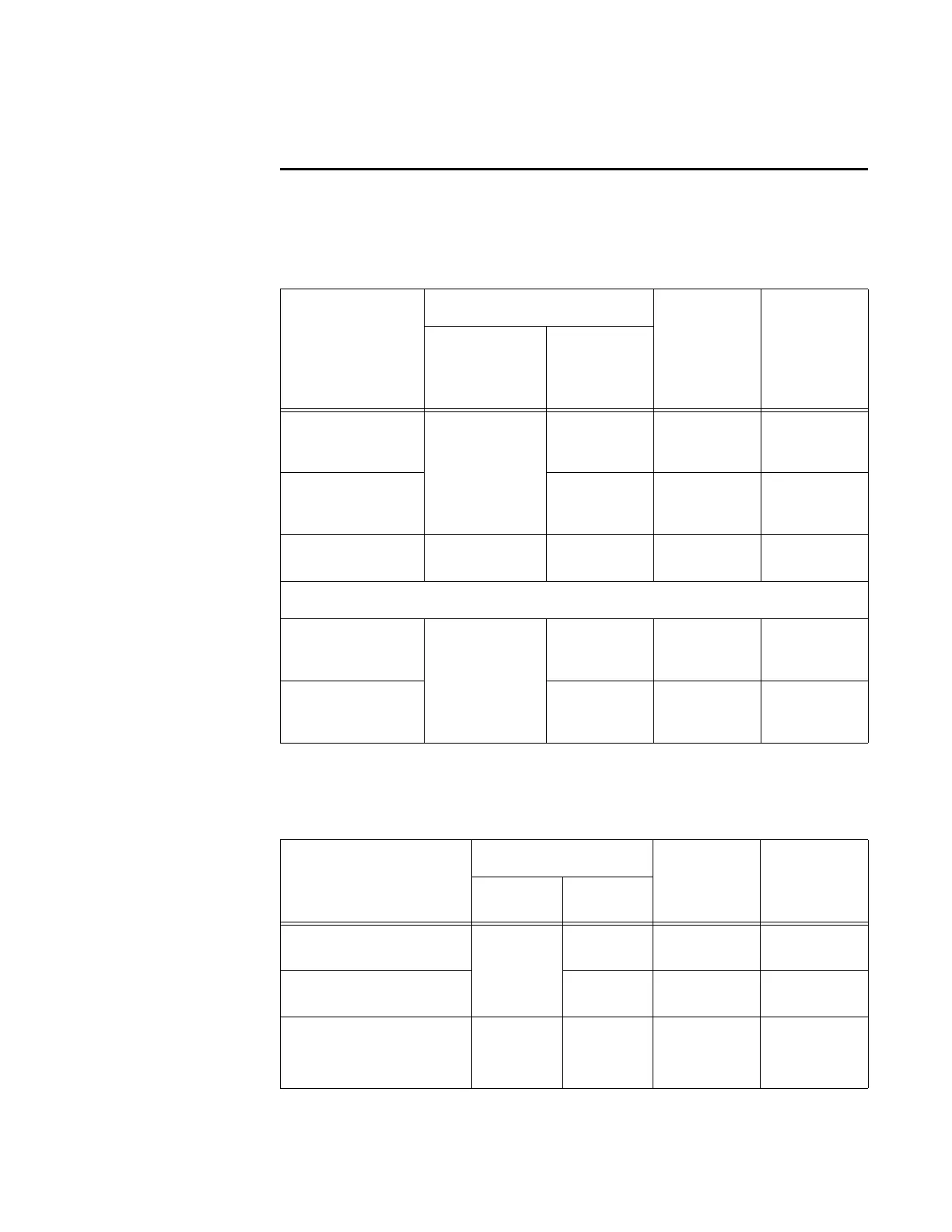
RS–232 Interface
Table C-2 shows the RS–232 assignments for colored-wire pair (13-pair) cable.
Table C-2 RS–232 Interface Signal Wiring for Colored-Wire Pair Cable
Signal from
Encompass
4 Re
ader
Colored-Wire Pair Cable
Connect
Wir
e to
Host DB9
Pin
Connect
Wire to
Host DB25
Pin
Wire Pair
fr
om
Encompass 4
Reader
Color Used
TxD —
Encom
pass
4 Reader output
Red/Black
Black Pin 2 Pin 3
RxD —
Encom
pass
4 Reader input
Red Pin 3 Pin 2
Signal ground Yellow/Black Yellow or
Black
Pin 5 Pin 7
Optional for hardware handshaking
RTS —
Encom
pass
4 Reader output
Yellow/Red
Yellow Pin 8 Pin 5
CTS —
Encom
pass
4 Reader input
Red Pin 7 Pin 4
Table C-3 shows the RS–232 assignments for alternate wire (15-pair) cable.
Table C-3 RS–232 Interface Signal Wiring for Alternate Wire Cable
Signal from
Enc
ompass 4 Reader
Alternate Wire Cable Connect
Wire to
Host DB9
Pin
Connect
Wire to
Host DB25
Pin
Pairing Color
TxD — Encompass
4 Reader output
Pair 1
Black Pin 2 Pin 3
RxD — Encompass
4 Reader input
Red Pin 3 Pin 2
Signal ground Pair 5 Black or
Red
Pin 5 Pin 7