Encompass 4 Reader System Guide
4-10
Connecting the DC Power Supply
To connect the Encompass 4 Reader to a low-voltage DC power supply
Caution
If you are using an external antenna, to avoid damage to the Encompass 4 Reader,
you
must connect the antenna before applying power to the reader.
1. Connect the Encompass 4 Reader power w
ires from the cable to the low-voltage
terminals using the connection designations shown in Table 4-3.
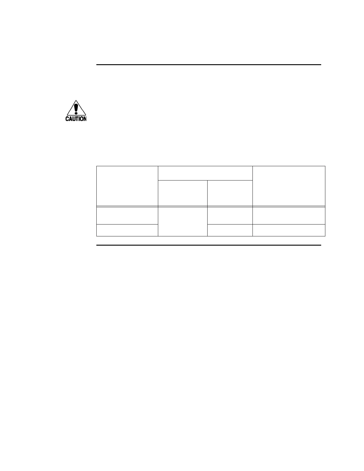
Table 4-3 Low Voltage DC Cable Connections for the Colored-Wire Pair Cable
Signal from
E
ncompass 4
Colored-Wire Pair Cable
Connection Use
Wire Pair from
Enc
ompass 4
Reader Cable
Color Used
Main power input Brown/Red and
Orange/Red
Orange and
br
own
16 to 28V DC+ terminal
Main power return Red and red 16 to 28V DC- terminal
Connecting Communications for Bench Testing
TransCore offers reader models that communicate through RS–232, RS–422, and
Wiegand interface protocols. This section describes the procedures and materials
required for connecting the communications to perform pre-installation bench testing
of the Encompass 4 Reader.
Required Materials
You need the following materials to connect the communications cable to the PC:
• PC or laptop
• Any terminal emulation program such as Procomm Plus™ or Hyper Terminal™
running on a PC
• Communications cable to connect to the COM1 port on your PC
Encompass 4 Reader communications and customer inte
rface signals are supplied
from the Encompass 4 Reader to the host through a multiwire cable, which is a 13-pair
pigtail. The connector for this cable is located on the back of the Encompass 4 Reader.
Refer t
o the following sections to connect the appropriate communications wires from
the cable to the PC.
These sections contain instructio
ns for connecting RS–232 and RS–422 communica-
tions between the Encompass 4 Reader and the
PC for bench testing purposes. Each