Encompass 4 Reader System Guide
C-4
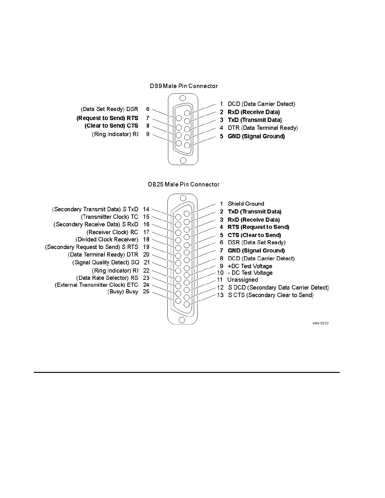
Figure C-1 DB9 and DB25 Connector Pin Assignments for Signal to Host
Note: In Figure C-1, supported pin assignments are boldface.
Cable Supplied with the Encompass 4 Reader
The Encompass 4 Reader is delivered with a multiwire cable (ordered as a separate
accessory), which is a 13-pair pigtail. An alternate 15-pair pigtail may be substituted.
The 13-pair pigtail is a colored-wire pair cable, with different colors denoting the indi-
vidual pairs, one pair of which is red/black. The alternate 15-pair pigtail is a red/black-
wire pa
ir cable, with numbers on the pairs to denote the individual pairs. Two pairs of
the 15-pair pigtail, numbers 14 and 15, are not used.
The following tables show the colored-wire pair (13-pair) and alternate wire pair
(15-pair) assignments for the various interface
s, power, and input/output connections.