Developing the Site Plan
2-19
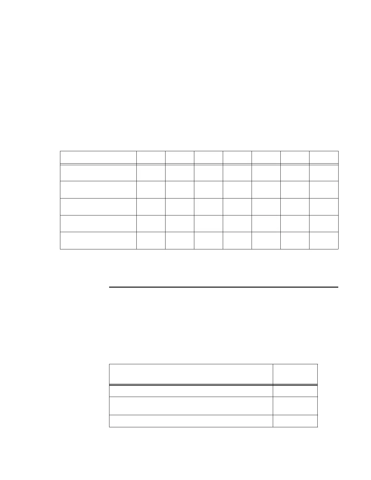
Gauge (AWG) standard for the necessary length of
extension cable. The numbers in
the first row of the table indicate cable size for the approximate cable length.
Note: If
the cable is close to the maximum length, measure voltage at the Encompass
4 Reader with RF ON to ensure voltage does not drop below 16V. A drop in voltage
below 16V causes a reduction in read range and possible damage to internal electron-
ics as well as unreliable operation.
Table 2-4 Recommended Cable Length from Transformer to the Encompass 4 Reader
Cable Size (AWG)
a
24 22 20 18 16 14 12
Maximum DCR (Ohms
pe
r foot at 68°F)
b
b. Direct current resistance (DCR) information is from the Belden catalog.
0.0270 0.0175 0.0109 0.0069 0.0044 0.0027 0.0017
TransCore 5-ft cable
(P/N 58-1620-001)
c
c. Based on a 1.0V drop at 1200 mA (RF ON) with 15% margin.
23 ft 36 ft 58 ft 92 ft 144 ft 235 ft 373 ft
TransCore 20-ft cable
(P/N 58-1620-002)
c
15 ft 23 ft 38 ft 60 ft 93 ft 152 ft 242 ft
TransCore 35-ft cable
(P/N 58-1620-006)
c
7 ft 11 ft 17 ft 27 ft 43 ft 70 ft 110 ft
TransCore 45-ft cable
(P/N 58-1620-007)
c
1 ft 2 ft 4 ft 6 ft 9 ft 14 ft 23 ft
Host Communications
Your site design must include communications between the Encompass 4 Reader and
a host computer. The Encompass 4 Reader communicates with the host computer
through an asynchronous serial line or through a Wiegand interface. This serial line
can be an RS
–232 interface or an RS–422 interface. The host computer must be able
to accept one of the interfaces shown in Table 2-5.
a. Use two pair (two conductors for power and two for return). TransCore cable is 22 AWG.
Table 2-5 Communications Interfaces and Conductor Requirements
Interface
Number of
Co
nductors
RS
–232 3
RS
–232 with RTS and CTS hardware and handshake
signals
5
RS
–422 4