Encompass 4 Reader System Guide
4-34
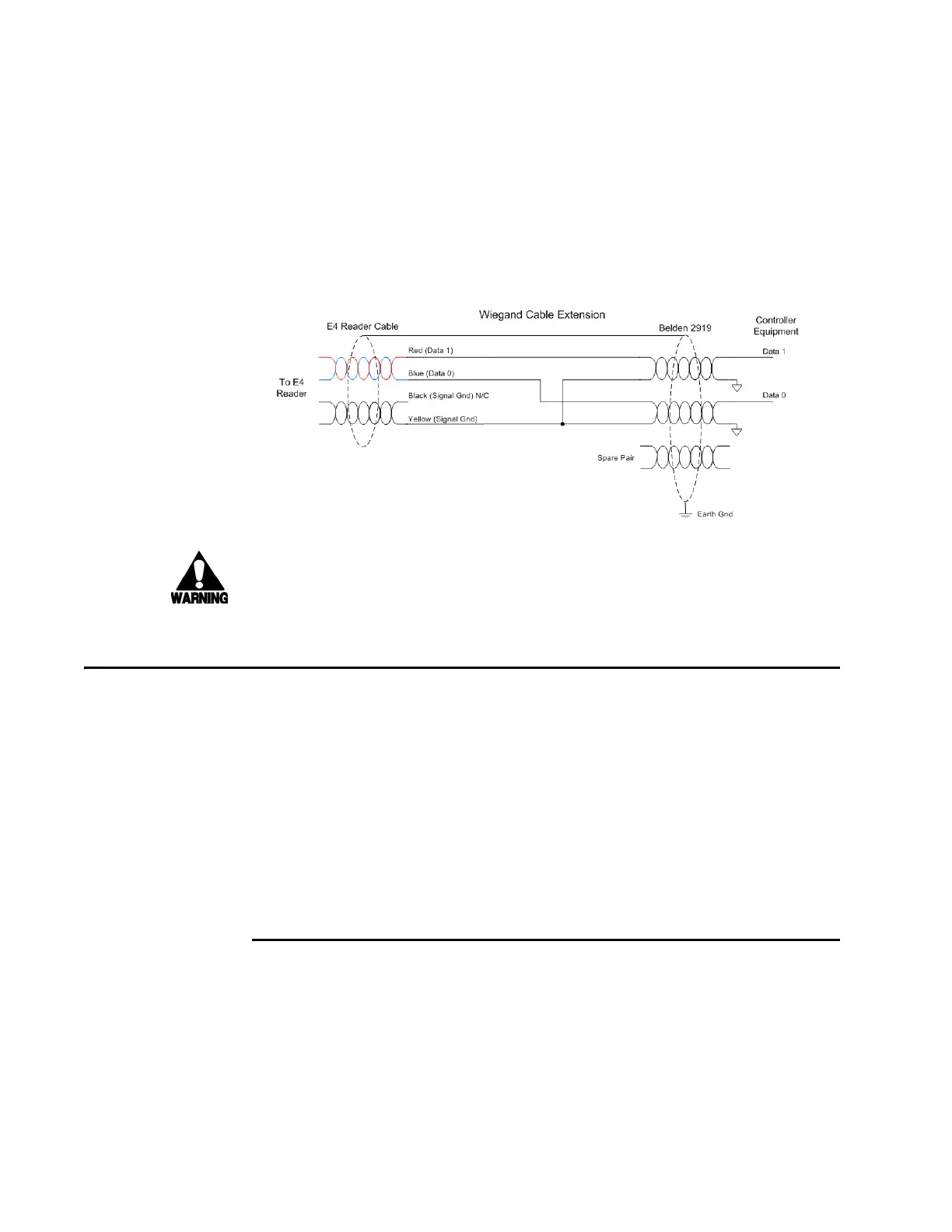
Note: When extending the
Wiegand interface, use a three-pair cable such as Belden
2919. Use a twisted pair for the Red (Data1) with ground (Yellow of the Black and Yel-
low pair), and a twisted pair for Blue (Data0) with ground (Yellow of the Black and
Y
ellow pair). The third pair of the three-pair cable can be used for a spare in the event
either of the other two pair are damaged or fail. The cable shield should be tied to a
single-point Earth Ground on the controller end of the cable. Refer to Figure 4-22.
Figure 4-22 Wiegand Cable Extension Diagram
Warning
Do not cut the RS–232 red/black wires. If you
cut the wires, you may not be able to
use them in the future for testing, setting frequency, or adding additional functions.
Connecting Sense Input and Sense Output Circuits
The Encompass 4 Reader has two sense input circuits and three sense output circuits
available. The sense input circuits can be used to notify the Encompass 4 Reader of
e
xternal events and are designed to be connected to a free-of-voltage dry contact.
Sense output circuits are single-pole, double-throw relays that provide normally
closed (NC) and normally open (NO) dry contacts. The relay contacts are rated at
42.2V AC peak (30 Vrms) or 60V DC at 1 A maximum. If controlling
an external gate
or device requiring high current, an isolation transformer is required.
The following sections provide information to connect the sense input
and sense out-
put circuits.
Sense Input Circuits
The Encompass 4 Reader supports two sense inputs – sense input0 and sense input1–
which requires two sense input lines for each loop sense or a total of four sense input
connections. Sense input0 is the presence detection device line and is used to control
RF power. As shown in Figure 4-23, sense input0 is through the red/green wire pair on
the I/O pigtail. The Encompass 4 Reader expec
ts the sense input0 circuit to close
when a vehicle is present (i.e., a NO condition). The minimum presence true period is