Installing the Encompass 4 Reader
4-35
fixed at 0 ms, which indicates that no delay
occurs in closing the circuit when a vehi-
cle is present.
Sense input1 allows the Encompass 4 Reader to
monitor the status of a peripheral
device. The host computer can then check the status by polling the Encompass 4
Reader.
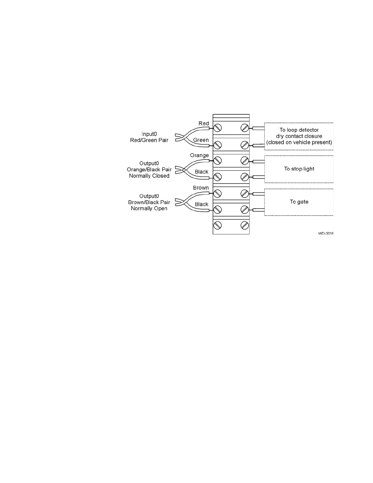
Figure 4-23 Sample Circuit Connections
For Encompass 4 Readers that are used with IAG protocols, the NC sense output0
common is connected to the NO sense output0 common via a jumper providing a
return for sense output0 NC. Figure 4-24 shows this wiring.