Wiring Tables
C-13
W Red Sense
Output0_NC
Sense Output0,
normally closed
terminal
Switched sense
output for any
external control (light,
gate, buzzer, etc.)
Pair 3 X Black Sense
Output1_COM
Sense Output1,
common terminal
Switched sense
output
Y Red Sense
Output1_NO
Sense Output1,
normally open
terminal
Switched sense
output
Pair 2 Z Black Sense
Output1_COM
Sense Output1,
common terminal
Switched sense
output
or Z** Black Sync_485_P RS–485 bus
positive
Used to connect
Encompass 4
Readers with IAG
capability on a
synchronization bus
a Red Sense
Output1_NO
Sense Output1,
normally closed
terminal
Switched sense
output
Pair 5 b Black GND logic ground Signal ground (used
with RS
–232 and
Wiegand
communications)
c Red GND logic ground Signal ground (used
with RS
–232 and
Wiegand
communications)
**Use this synchronization pin designation if installing an Encompass 4 Reader that reads IAG
protocol tags. The part numbers for these readers are as follows:
10-4002-004; 10-4002-010; 10-4002-019; 10-4004-004; 10-4004-010; 10-4004-019;
10-4012-004; 10-4012-010; 10-4012-019; 10-4014-004; 10-4014-010; 10-4014-019
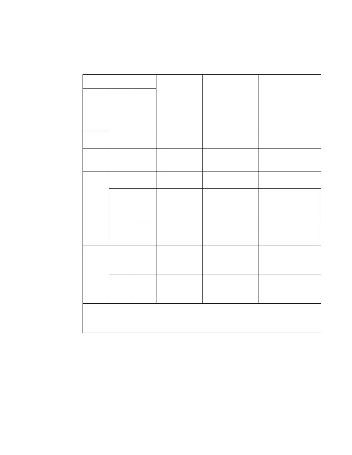
Table C-13 Sense Input/Output Cabling Assignments for Alternate Wire Cable
Alternate Wire
Signal Description Typical Function
Pairing Pin Color