FRAME E
SECTION
EI
REMOVING
AND
REPLACING
THE
FUEL
TANK
\
.~
Turn
both fuel taps
to
the
"off"
position, then
unscrew bach unions and
disconnect
the
feed pipes
at the taps.
Open
the
twin
seat,
then
unscrew
the
rear securing
screw
complete
with
mounting
rubbers, cups, etc. Carefully
note
the
order
of
assembly.
Raise
the
rear
end
of
the
tank
and
then
11ft
the
whole
tank upwards
to
draw
It off
the
rubber
buffers
attached
to
the
frrme
top
tube,
and which locate
In
pockets
In
the
tank
center
tunnel. Take great care
not
to
damage the tank
enamel.
When
re-mountlng
the
tank,
these
buffers must be
retained, because
they
prevent
metal-co-metal
contact
between
tank
and frame. Fit
the
front end
first, and
lower
the
rear
end
Into
position. Re-
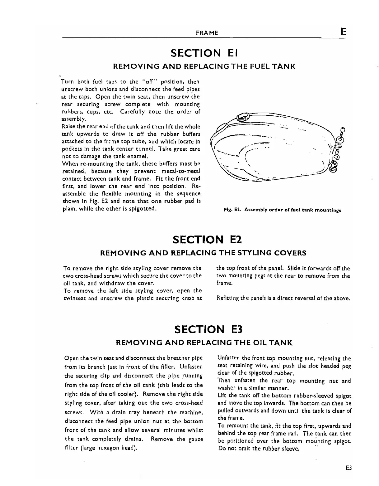
assemble
the
flexible
mounting
in
the
sequence
shown
In
Fig.
E2
and
note
that
one
rubber
pad
Is
plain, while
the
other
Is
splgotted.
--.
.
-
FIg.
E2.
Assembly
order
of
fuel
tank
mountIngs
SECTION
E2
REMOVING
AND
REPLACING
THE
STYLING
COVERS
To
remove
the
right side styling
cover
remoVe
the
two
cross-head screws which
secure
the
cover
to
the
oil tank, and wlthd raw
the
cover.
To remove
the
left side styling
cover,
open
the
twlnseat
and
unscrew
the
plastic securing knob at
the
tOP
front of the panel. Slide
It
forwards off
the
two mounting pegs at
the
rear
to
remove from the
frame.
Refitting the panels
Is
a
direct
reversal of
the
above.
SECTION
E3
REMOVING
AND
REPLACING
THE
OIL
TANK
Open
the
twin seat and
disconnect
the
breather
pipe
from
Its
branch just
In
front
of
the
filler. Unfasten
the
securing clip and
disconnect
the
pipe running
from
the
top
front of
the
oil
tank
(this leads
to
the
right side
of
the
all cooler). Remove
the
right side
styling cover, after taking
out
the
tWO
cross-head
screws.
With
a drain
tray
beneath
the
machine,
disconnect
the
feed pipe union nUt
at
the
bottom
front
of
the
tank and allow several minutes whilst
the
tank completely drains. Remove
the
gauze
filter (large hexagon head).
Unfasten
the
front top mounting nut, releasing
the
seat retaining wire, and push
the
slot headed peg
clear of the splgotted
rubber.
Then unfasten the
rear
top
mounting
nut
and
washer
In
a similar manner.
Lift
the tank off
the
bottom
rubber-sleeved spigot
and move
the
top Inwards. The
bottom
can then be
pulled outwards
and
down until
the
tank
Is
clear of
the
frame.
To remount
the
tank, fit
the
top
first, upwards and
behind
the
top rear frame rail. The
tank
can then
be
positioned over
the
bottom
mou'ntlng spigot.
Do
not omit
the
rubber sleeve. "
E3