G
TELESCOPIC
FORKS
Take
off
the
nuts
under the
top
yoke, whIch
secure
the
handlebar brackets, then
11ft
off
the
handlebars
and
lay
them
on
the
tank, using a thick
piece
of
cloth
or
something
similar
to
prevent
scratching
Remove
the
two
forward facing bolts whlLh
secure
the
binnacle assembly
to
the
top
yoke, and discon-
nect
the
drives
to
the tachometer
and
speedometer.
Slacken
the
screW on
top
of
the
head lamp shell and
prise
off
-the
rim.
Disconnect
the
green leads
from
the
front
flasher lamps, and remove
the
lamps and
stalks (See Section H14). Remove
the
headlamp
and Its
mounting,
and
lay
It aside,
together
with
the
binnacle assembly.
Disconnect
the
front
brake pipe unions and
remove
the
pipes.
If
it
Is
necessary
to
remove
the
brake
caliper, see Section
F13.
Remove
the
dust
cover from
the
top
of
each
fork
stanchion
by unscrewing
In
an
anti-clockWise
dlrec-
tlon.
Unscrew
the
two
socket type clamp bolts,
located
at
the
rear
of
the
top
fork yoke, and
then
unscrew
the
alun-Inium cap
screw
from
the
top
of
each stanchion using a suitable sized
socket
wrench.
Remove
the
Internal fork springs. Using Service
Tool
61-6113
placed down Into
the
stanchion, hold
the
valve assembly while
the
retaining
socket
screw
In
the
base
of
the
fork leg
Is
being
unscrewed.
The
tip
of
Service Tool
61-6113
Is
rounded.
For
more
recent
forks,
it
will
be
advantageous
to
grind
a flat
on
the
tip, making it
screwdriver
shaped.
At
this stage,
it
will be possible
to
remove
the
fork
leg by sliding It from
the
stanchion. Slacken
the
pinch bolts
on
the
bottom yoke
In
order
to
with-
draw
the
stanchion.
When
refitting,
tighten
the
pinch bolts
to
2S
Ibs/ft.
The
dust
cover
on
the
fork leg can easily be prlsed
off by hand.
The
damFer valve
Is
retained
In
the
bottom
of
the
stanchion
by
an
alumlnlu",
nut
which
should be carefully removed with a ring
spanner
or
similar tool.
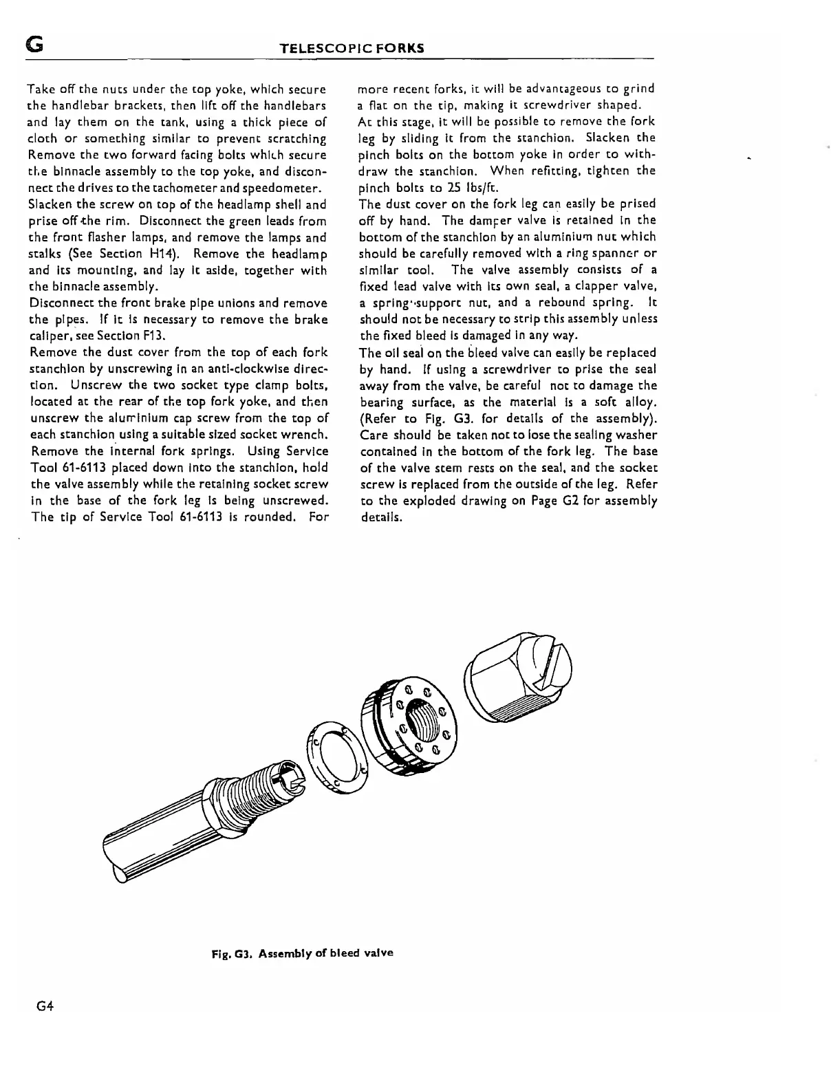
The
valve assembly consists
of
a
fixed lead valve with its own seal, a clapper valve,
a
sprlng"support
nut, and a rebound
spring.
It
should
not
be
necessary to
strip
this assembly unless
the
fixed bleed
Is
damaged
In
any way.
The
011
seal
on
the
bleed valve can easily be
replaced
by hand.
If
using a
screwdriver
to
prise
the
seal
away from
the
valve, be careful
not
to damage
the
bearing surface,
as
the material
Is
a
soft
alloy.
(Refer
to
Fig.
G3. for details
of
the assembly).
Care
should be taken
not
to
lose
the
sealing
washer
contained
In
the
bottom
of
the
fork leg.
The
base
of
the
valve
stem
rests on
the
seal,
and
the
socket
screw
Is
replaced from
the
outside
of
the leg. Refer
to
the
exploded drawing on Page
G2
for assembly
details.
Fig. G3. Assembly
of
bleed valve
G4