c
PRIMARY
DRIVE
Straighten
the
tabs
of
the
locking plates and remove
the
six
bolts
retaining
the
outer
plate. After
the
screws
are removed.
the
plate can be lifted off
and
the
rubber
segments exposed. At this stage,
the
hexagon
portion
of
the
leverage bar
'should
be
placed
In
the
splines
of
the
shock
absorber
spider.
A
strong
pull on
the
bar will then
rotate
the
spider,
and
compress
one
set
of rubbers. The bar will be
held
In
this portion
by
Inserting a
screwdriver
blade
or
a
tommy
bar
through
the
hole
In
the
bar
to
engage
with
the
sprocket
teeth.
The
first
set
of
rubbbers
can then be lifted oUt. Carefully restrain
the
bar
whilst
the
screwdriver blade
Is
withdrawn.
At
this
stage
the
remaining sets
of
rubbers
will be
free
for
removal, and
the
spider can be lifted oUt.
One
type
of
rubber
is
used for both drive and
rebound.
Fit
the
new rubbers Into place, using
the
mounting
Jig
and bar. Then fit
the
retaining
plate. followed
by
the
locking plates and
the
bolts. securing these with
the
tabs
of
the
locking
plates.
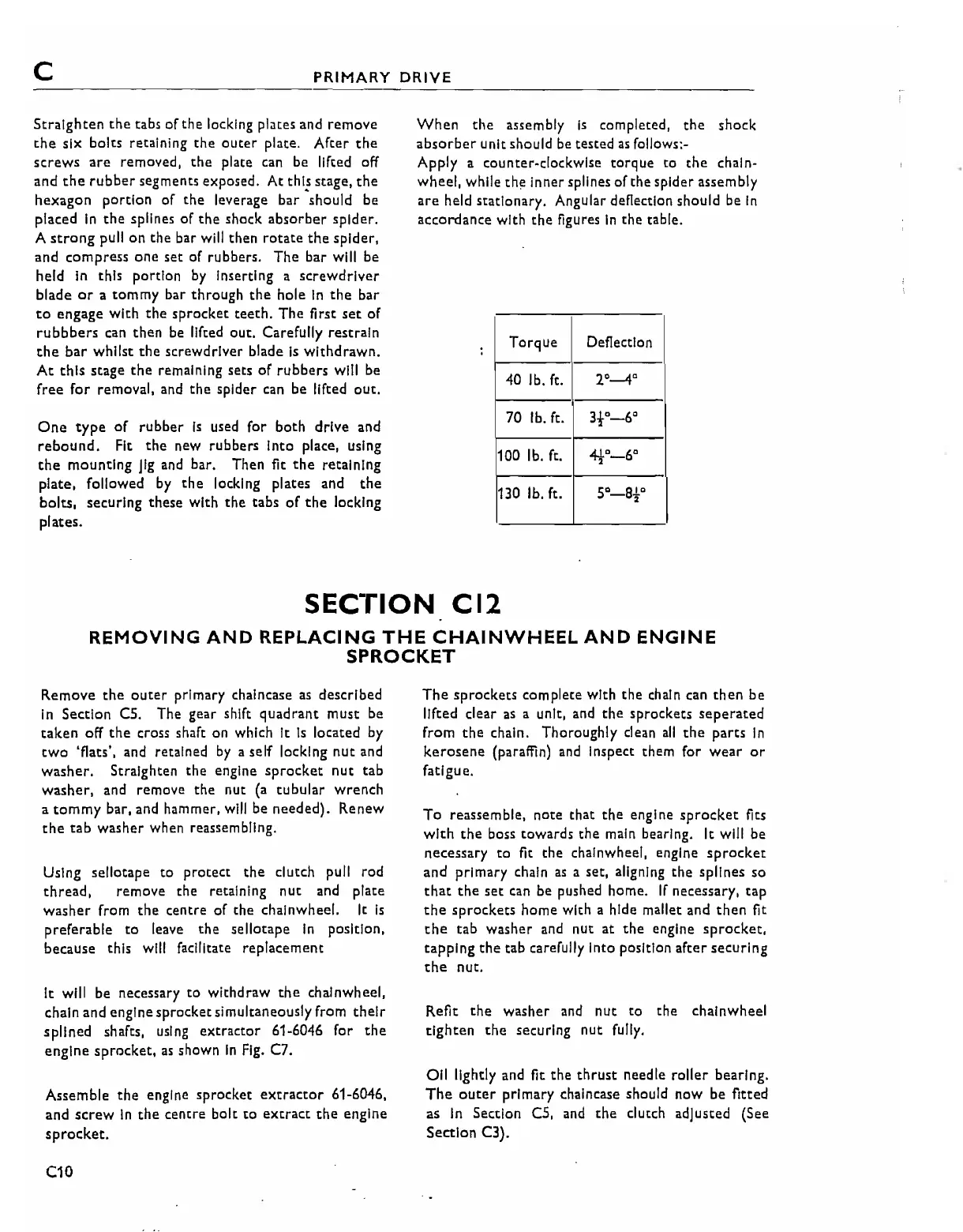
When
the
assembly
is
completed,
the
shock
absorber
unit should be tested
as
follows:-
Apply a counter-clockwise
torque
to
the
chain-
wheel, while
the
Inner splines
of
the spider assembly
are
held stationary. Angular defiection should be
In
accordance with
the
figures
In
the
table.
Torque
Defiectlon
40 lb. ft.
2°-4
0
70 lb. ft.
3to-6°
100 lb. ft.
4t
D
_
6
°
130 lb. ft.
5°_
B
t
C
SECTION
CI2
REMOVING
AND
REPLACING
THE
CHAINWHEEL
AND
ENGINE
SPROCKET
Remove
the
outer
primary chaincase
as
described
In
Section
CS.
The gear shift
quadrant
must be
taken
off
the
cross shaft on which It
Is
lotated
by
two
'flats', and retained
by
a self locking
nut
and
washer.
Straighten
the
engine
sprocket
nut
tab
washer,
and
remove
the
nut
(a
tubular
wrench
a
tommy
bar, and hammer.
will
be needed). Renew
the
tab
washer when reassembling.
Using sellotape
to
protect
the
clutch pull rod
thread, remove the retaining
nUt
and
plate
washer
from
the
centre
of
the chainwheel. It
is
preferable
to
leave
the
sellotape
in
position.
because this will facilitate replacement
It will be necessary
to
withdraw
the
chainwheel,
chain and engine sprocket simultaneously from
their
splined shafts, using
extractor
61-6046 for
the
engine
sprocket,
as
shown
In
Fig.
C7.
Assemble
the
engine sprocket
extractor
61-6046,
and
screw
In
the
centre bolt
to
extract
the
engine
sprocket.
C10
The
sprockets
complete with
the
chain can
then
be
lifted clear
as
a unit, and
the
sprockets
seperated
from
the
chain. Thoroughly clean
all
the
parts
In
kerosene
(paraffin) and Inspect them for
wear
or
fatigue.
To
reassemble, note that
the
engine
sprocket
fits
with
the
boss towards
the
main bearing. It will be
necessary
to
fit the chainwheel, engine
sprocket
and primary chain
as
a set, aligning
the
splines so
that
the
set
can be pushed home.
If
necessary,
tap
the
sprockets
home with a hide mallet and
then
fit
the
tab
washer and nut at
the
engine
sprocket,
tapping
the
tab carefully into position
after
securing
the
nut.
Refit
the
washer and
nut
to
the
chainwheel
tighten
the
securing
nut
fully.
Oil lightly and fit
the
thrust
needle
roller
bearing.
The
outer
primary chaincase should now be fitted
as
In
Section C5, and
the
clutch adjusted (See
Seetlon C3).