ENGINE
B
ALTITUDE
The settings given on page
GD4
are
those
normally
recommende':; and will
be
suitable
for most
atmospheric conditions.
They
are
Intended for
altitudes up
to
3,OOOft.
(1000m).
Above
this height
some reduction
in
main Jet size is necessary
to
provide a balanced
mixture.
For
altitudes
between
3,000 ft. and 6,000 ft. (2,000 m.) a
reduction
In
main
Jet size by 5
per
cent
Is
usually necessary, and for
every 3,000 ft. Increase
over
6,000 ft. a
furtherA
per
cent
Is
required.
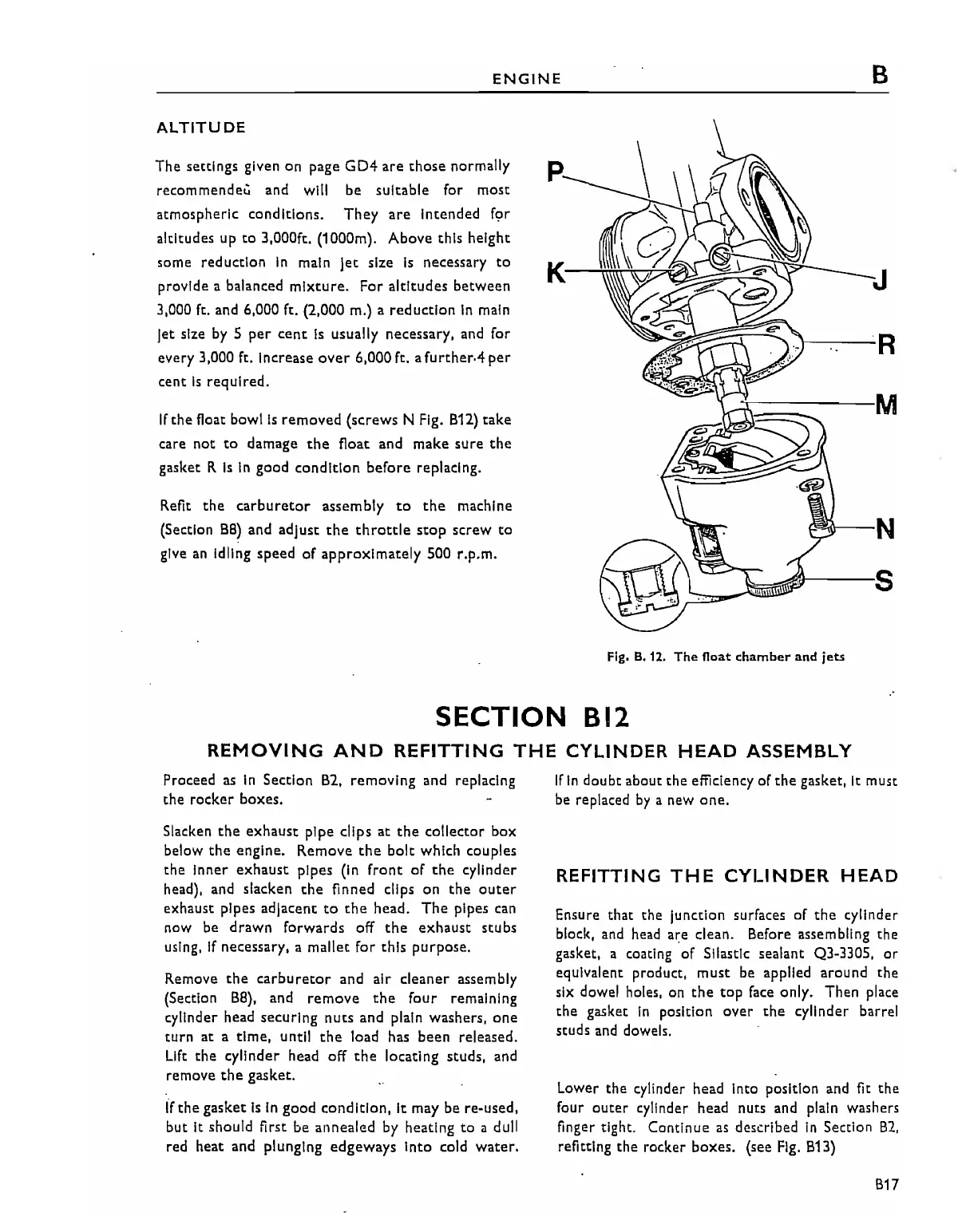
If
the
float bowl
Is
removed
(screws
N Fig.
B12)
take
care not
to
damage
the
float
and
make sure the
gasket R
Is
In
good
condition
before
replacing.
Refit
the
carburetor
assembly
to
the
machine
(Section
BB)
and
adjust
the
throttle
stop
screw
to
give
an
Idling speed
of
approximately
500 r.p.m.
p
K
J
IIl---N
Fig.
B.
12.
The float chamber and
jets
SECTION
812
REMOVING
AND
REFITTING
THE
CYLINDER
HEAD
ASSEMBLY
Proceed
as
In
Section
B2,
removing
and replacing
the
rocker
boxes.
Slacken
the
exhaust
pipe clips
at
the
collector
box
below
the
engine. Remove
the
bolt
which couples
the
Inner
exhaust
pipes (In
front
of
the
cylinder
head), and slacken
the
finned clips on
the
outer
exhaust pipes adjacent
to
the
head.
The
pipes can
now be
drawn
forwards
off
the
exhaust
stubs
using,
If
necessary, a mallet for this purpose.
R.emove
the carburetor
and
air cleaner
assembly
(Section
BB),
and
remove
the
four
remaining
cylinder head
securing
nuts
and plain washers,
one
turn
at a
time,
until
the
load has been released.
Lift
the
cylinder head off
the
locating studs, and
remove
the
gasket.
if
the
gasket
Is
In
good
condition,
It may
be
re-used,
but It should first
be
annealed by heating
to
a dull
red heat and plunging
edgeways
Into cold
water.
If
In
doubt about
the
efficiency
of
the
gasket, It must
be replaced
by
a new
one.
REFITTING
THE
CYLINDER
HEAD
Ensure that
the
Junction surfaces
of
the
cylinder
block, and head are clean. Before assembling the
gasket, a coating
of
Sllastlc sealant Q3-330S,
or
equivalent product,
must
be applied
around
the
six dowel holes, on
the
top
face only.
Then
place
the
gasket
In
position
over
the
cylinder
barrel·
studs and dowels.
Lower
the
cylinder head Into position and fit
the
four
outer
cylinder head nuts and plain washers
finger tight. Continue
as
described
In
Section
B2,
refitting
the
rocker boxes. (see
Fig.
B13)
B17