H
ELECTRICAL SYSTEM
SECTION
19
THE
STARTER
MOTOR
CIRCUIT
DESCRIPTION
The
starter
motor
circuit
consists
of
the
handleba.r
starter
switch,
the
starter
relay,
the
electric
starter
motor, an electric solenoid, a
housing
with bearings, an
intermediate
shaft, a
lever
mechanism,
and an engaging pinion.
:=-...;;
J.
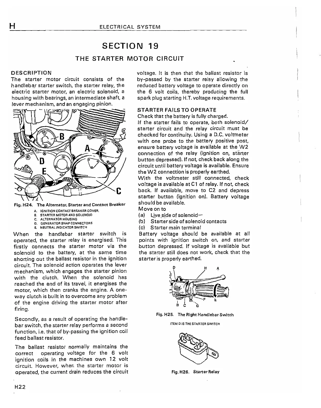
Fig.
H24.
The
Alternator,
Starter
and Contact Breaker
A.
IGNITION
CONTACTBREAKEA
COVER.
8. STARTER MOTOR AND SOLENOID
C.
ALTERNATOR HOUSING
O.
GENERATOR SNAP CONNECTORS
E.
NEUTRAL INDiCATOR
SWITCH
When
the
handlebar
starter
switch
is
operated,
the
starter
relay
is
energised. This
firstly
connects
the
starter
motor
via
the
solenoid
to
the
battery,
at
the
same
time
shorting
out
the
ballast resistor
in
the
ignition
circuit. The solenoid action
operates
the
lever
mechanism,
which
engages
the
starter
pinion
with
the
clutch. When
the
solenoid
has
reached
the
end
of its travei, it
energises
the
motor,
which then cranks
the
engine. A
one-
way
clutch
is
built
in
to
overcome
any problem
of
the
engine driving
the
starter
motor
after
firing.
Secondly,
as
a result of operating
the
handle-
bar
switch,
the
starter
relay performs a
second
function,
Le.
that
of by-passing
the
ignition coil
feed
ballast resistor.
The
ballast resistor normally maintains
the
correct
operating voltage for
the
6 volt
ignition coils
in
the machines
own
12
volt
circuit. However, when
the
starter
motor
is
operated,
the
current drain
reduces
the
circuit
H22
voltage.
It
is
then
that
the
ballast resistor is
by-passed
by
the
starter
relay allowing
the
reduced
battery voltage to
operate
directly on
the
6 volt coils, thereby producing
the
full
spark
plug starting
H.T.
voltage requirements.
STARTER
FAILS TO OPERATE
Check
th'at
the
battery
is
fully
charged.
If
the
starter
fails to operate, both
solenoidl
starter
circuit and
the
relay circuit
must
be
checked
for continuity. Using a
D.C.
voltmeter
with
one probe to
the
battery positive post,
ensure
battery voltage
is
available
at
the
W2
connection
of
the
relay (ignition on,
starter
button
depressed).
If
not, check back along
the
circuit until battery voltage
is
available. Ensure
the
W2
connection is properly earthed.
With
the
voltmeter still connected,
check
voltage
is available
at
C1
of relay.
If
not,
check
back.
If
available, move to C2 and
depress
starter
button (ignition on). Battery voltage
should
be available.
Move
on to
(a)
Live_side
of
solenoid-
(b)
Starter
side of solenoid
contacts
(c)
Starter
main terminal
Battery
voltage should be available
at
all
points
with ignition switch on, and
starter
button
depressed.
If
voltage
is
available
but
the
starter
still
does
not work, check
that
the
starter
is
properly earthed.
H
~
Fig.
H25. The Right Handlebar Switch
ITEM 0 IS THE STARTER SWITCH
Fig.
H26.
Starter
Relay