ENGINE
B
It
Is
advisable
at
this
sugeto
remove
the
oil
pressure release valve (Section A6).
The
tacho-
meter
drive can
now
be
removed
from
the
crankcase
(Section 836).
Remove four self locking nUts and
washers
from
the
main bearing caps, and
as
the
caps
are
located on
waisted studs.
the
crank
should
be
lifted
to
free
them.
Under
no
circumstances
should
the
caps
be
prised
off. After removing
the
crankshaft
the
connecting rods and big end shells can be removed.
The caps are retained by self locking
nuts,
and
after
removal of
the
connecting rods
the
caps should be
refitted
to
them
to
ensure
that
they
are
reasembled
to
the
corresponding connecting
rods.
The gearbox
sprocket
and high
gear
should be
removed (Sections D7, D11)
In
order
to
check
the
condition of
the
high
gear
bearing
and
oil seal.
If
these parts
are
worn
they
should
be
replaced. Do
not
attempt
to
use a seal which has
shown
signs of
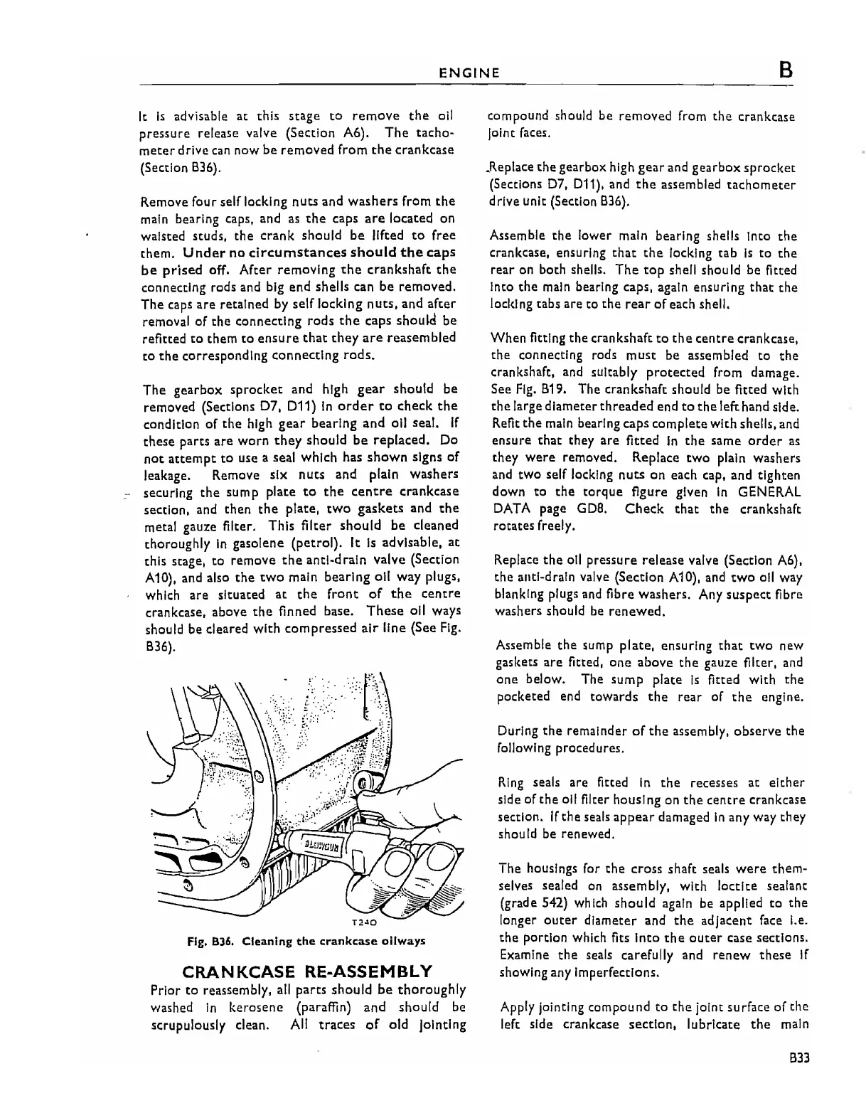
leakage. Remove six
nuts
and plain washers
securing the sump plate
to
the
centre
crankcase
section. and then
the
plate.
two
gaskets
and
the
metal gauze filter. This filter
should
be
cleaned
thoroughly
In
gasolene (petrol). It
Is
advisable.
at
this stage.
to
remove
the
anti-drain valve (Section
A10), and also
the
two
main bearing oil way plugs,
which are situated
at
the
front
of
the
centre
crankcase. above
the
finned base.
These
oil ways
should be cleared with compressed
air
line (See
Fig.
836).
Fig. 836.
Cleaning
the
crankcase
oilways
CRANKCASE RE-ASSEMBLY
Prior
to
reassembly,
all
parts should
be
thoroughly
washed
in
kerosene (paraffin)
and
should
be
scrupulously
dean.
All
traces
of
old Jointing
compound should be removed from
the
cranktase
joint faces.
.Replace
the
gearbox high
gear
and gearbox
sprocket
(Sections
D7,
011). and
the
assembled
tachometer
drive unit (Section 836).
Assemble
the
lower main bearing shells Into
the
crankcase. ensuring
that
the
locking tab
Is
to
the
rear on both shells.
The
top
shell shou
Id
be fitted
Into the
main
bearing caps,
again
ensuring that the
locking tabs are to
the
rear
of
each shell.
When fitting the crankshaft
to
the
centre
crankcase,
the connecting rods must be assembled to
the
crankshaft, and sUitably
protected
from damage.
See
Fig.
819. The crankshaft should be fitted with
the
large diameter
threaded
end
to
the
left hand side.
Refit
the
main bearing caps complete with shells. and
ensure
that
they are fitted
In
the
same
order
as
they
were
removed. Replace
two
plain washers
and two self locking
nuts
on
each cap, and tighten
down
to
the
torque
figure given
In
GENERAL
DATA
page
GDB.
Check
that
the
crankshaft
rotates freely.
Replace
the
oil pressure release valve (Section A6),
the anti-drain valve (Section A10). and
tWO
oil way
blanking plugs and fibre washers. Any suspect fibre
washers should
be
renewed.
Assemble the
sump
plate. ensuring that
two
new
gaskets are fitted,
one
above
the
gauze filter.
and
one below. The sump plate
Is
fitted with the
pocketed end towards
the
rear
of
the
engine.
During
the
remainder
of
the
assembly, observe the
following procedures.
Ring
seals are fitted
in
the
recesses at
either
side of the all filter housing on
the
centre
crankcase
section.
If
the
seals
appear
damaged
In
any way they
should be renewed.
The housings for
the
cross shaft seals
were
them-
selves sealed
on
assembly, with
loctlte
sealant
(grade S42) which
should
again be applied
to
the
longer
outer
diameter and
the
adjacent face I.e.
the
portion which fits Into
the
outer
case sections.
Examine
the
seals carefully and
renew
these
if
showing any Imperfections.
Apply jointing compound
to
the
joint surface of the
left side crankcase section, lubricate
the
main
833