TELESCOPIC
FORKS
_._---
------------_._._-_.-
--------
SECTION
G4
FORK
ALIGNMENT
G
After replacing the fork legs, mudguard,
and
wheel,
It
may
be
found
that the legs are incorrectly
aligned.
To rectify this,
the
wheel
spindle
cap
nuts
mL'st
first be
screwed
lip
tight
on
the
right
side
leg and
the
spindle cap nuts
on
the
left side ieg slackenEd
off. Also loosen
the
stanchion
tOP
caps
and
the
pinch baits
in
both
the
bottom
and
top
yokes.'
The
forks should now
be
worked
lip
and
down
several
tImes
to
line
them
up, and
the
various
connec-
tions tightened from
bottcm
to
lop.
that
Is,
\\htel
spindle.
bottom
yoke
pinch bolts,
top
caps and
finaliy,
the
steering
stem
pinch
bolt
In
the
top
yoke.
If,
after this
treatment,
the
forks still do
not
functicn satisfactorily
then
eld.Er
the
fork
stan-
chions
are bent
or
one
of
the yokes
Is
tWls~ed.
The
stanctions
can
only
be
accurately
checked
for
straightness
with
special
eqUipment
such
as
a
surface plate. Special gauges
are
also required
to
ch<ek
the
yokes, It
Is
possible.
however,
to
make a
reasonable check
of
the
stanctlons
by
relling
them
on a surface plate
or
flat surface such as a piece
of
plate glass,
but
It
Is
not
a
sl
mple
operation
to
straighten a bent tube,
and
a new part
may
be
necessary.
Check
the
stanctlons
for
truth
by rolling
them
slowly on a flat chEcking
table.
A
bent
stantelon
may
be rea
II
ned
if
the
"bow"
does
not
exceed
3
5
2 in.
To
realine
the
stanction.
a hand press
Is
required. Place
the
stanction
on
two
"V"
blocks,
one
at
either
end, and apply
pressure
to
the
raised portion
of
the
stanctlon.
By
means
of
al<ornately pressing
In
this
way. and checking
the stanction on a nat table.
the
amount
of
bow
can
be
reduced until
it
is
finally
removed.
Having checked the
stanctions
for straightness. and
reset
as
necessary.
the
top
and
bottom
yokes
can
now
be
checked. First,
assemble
the
two
stanctions
into the bottom
yoke.
so
that a straight
edge
across
the
lower
ends
Is
touching
all
four
edges
of
the
tubes, then tighten
the
pinch
bolts.
Now
examine
them from
the
side
when
the
two
stanctlons should
be
quite
parallel.
Alternatively.
the
lower
12 in. of
the
stanctions
can
be placed
on
a surface plate,
"hen
there
should be
no
rocking.
To reset, hold
one
stanctlon
I.n
a vice (using
soft
c1amFs)
and
reset
the
other
stanctlon, using a
longer
and
larger
diameter
tube
so
to
obtain
sufficlant leverage. Having
checked
the
stanctions
In
this way. check
the
gap
between
them.
The
neXt
step
Is
to
place
the
bottom
yoke
In
position
over
the
stanctlons,
and tighten
the
clip
bolts. when
the
steering
stem
should
be
centrally
disposed
between
the
two
stanctions.
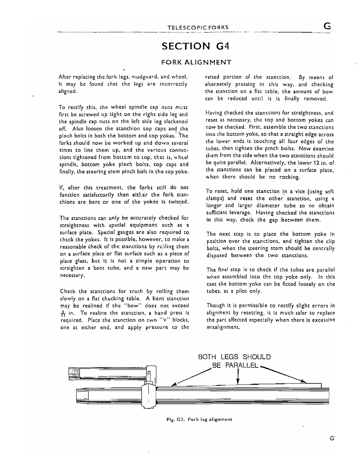
The
final
step
Is
to
check
If
the
tubes
are
parallel
when assembled Into
the
top
yoke
only.
in
this
caes the
bottom
yoke
can be fitted loosely
on
the
tubes.
as
a pilot only.
Though it
is
permissible
to
rectify slight
errors
In
alignment
by
resetting. it
Is
much safer
to
replace
the part affected especially
when
there
Is
excessive
misalignment.
Fig.
G'l.
Fol'lt
I~g
alignrnf:llt
G7