E
FRAME
SECTION
E9
REMOVING
AND
REFITTING
THE
SWINGING
FORK
Set
the
machl~le
on
Its
centre stand so that
the
rear
wheel
Is
clear
of
the
ground.
Remove
both
mufflers, which are attached
to
the
pillion
faatpeg
plates
by.
bolts, and
by
clips
to
the
exhaust
collector
box
beneath
the
engine.
Take
off
the
left side styling panel (Section
E2)
to expose the
chalnguar.d
front connection,
and
unscrew
the
bolt. Remove
the
bolts securing
the
lower
ends
of
the
shock
absorbers
to
the
swinging
arm.
This will also release
the
rear
fixing point
of
the
chalnguard, leaving It free
for
removal.
Uncouple
the
rear
chain
at
Its
spring
link,
and
remove
It
from the rear sprocket.
Do
not unwind
It
from
the
transmission
sprocket,
because this will
greatly
simplify replacement
of
the
chain. Discon-
nect
the
speedamet~r
driving cable
at
Its union
with
the
gearbox
.on
the
rear
wheel, which will
then
leave
the
wheel ready
for
removal (see Section
F17).
-'
Remove
the
wheel.
Before
the
fork spindle becomes accessible, It
Is
necessary
to
remove the rear engine plates,
together
with
ancillary fittings. Unscrew
all
the
bolts
securing
the
left side yoke plate, noting
the
position
of
the
washers and distance pieces.
When
the
plate
Is
removed,
the
faatpeg may remain
undisturbed.
On
the
right side
of
the
machine,
the
torGue
arm
which
carries
the
brake caliper
Is
attached
to
the
swinging
arm
by
a
short
link. Remove
the
bolt
at
the
upper
connection and
note
the
position
of
the
washers.
These
are
situated so
that
the
link
Is
free
to
re-allgn Itself when
the
wheelis
removed
during
chain
adjustment
and
the
washers
must
be replaced
In
their
original position.
The
securing
nUt
Is
of
the
self-locking type and It
Is
advisable
to
fit a
new
one
when
re·assembllng.
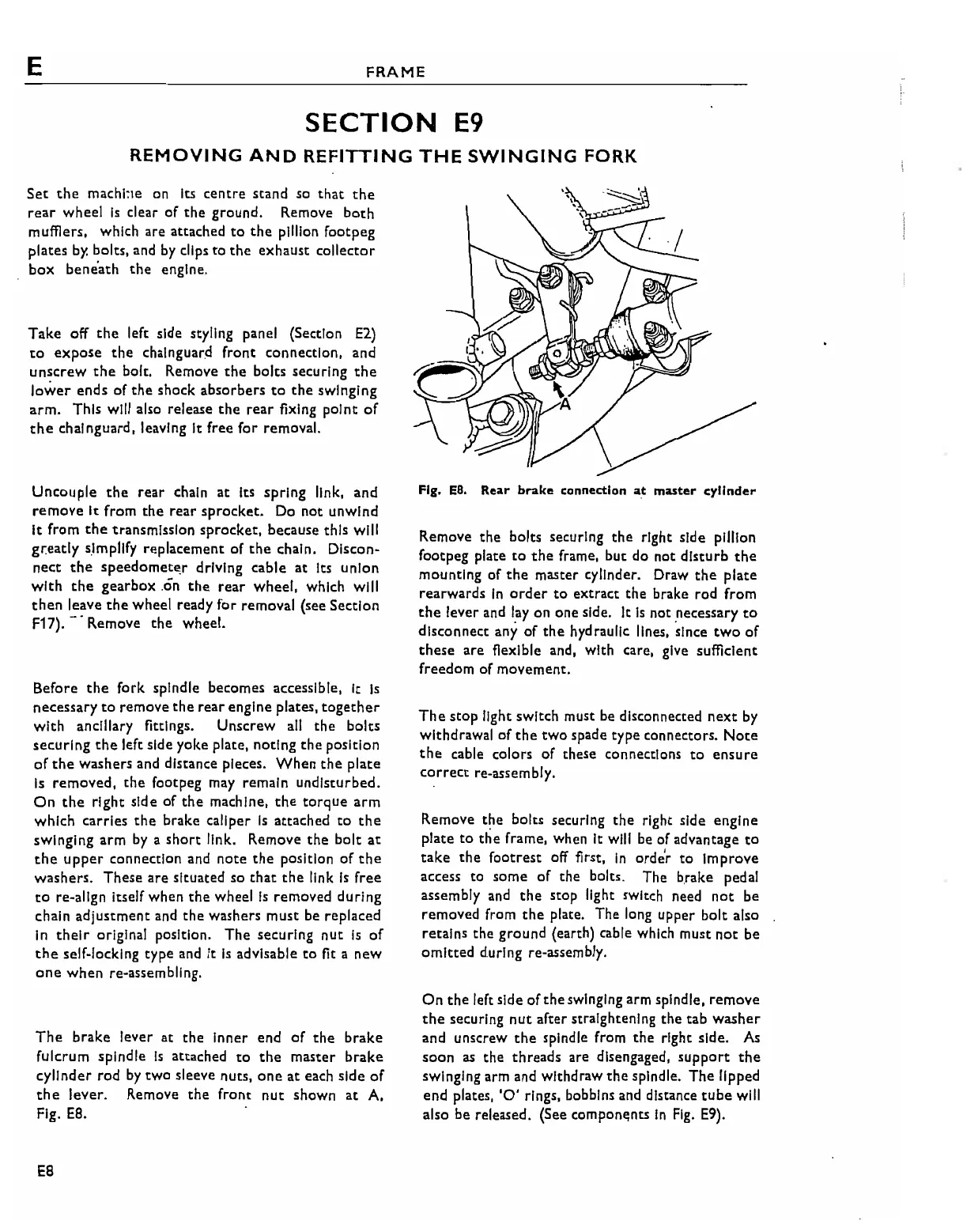
The
brake
lever at
the
Inner end
of
the
brake
fulcrum spindle
Is
attached
to
the
master
brake
cylinder
rod
by
twO
sleeve nuts,
one
at
each side
of
the
lever.
Remove
the
front
nut
shown
at
A,
Fig.
E8.
E8
Fig.
EO.
Rear
brake
connection
a.t
master
cylinder
Remove
the
bolts securing
the
right side pillion
foot
peg plate
to
the
frame, but do not
disturb
the
mounting
of
the
master cylinder. Draw
the
plate
rearwards
In
order
to
extract the brake rod from
the
lever and lay on one side. It
Is
not necessary
to
disconnect any
of
the
hydraulic lines,
~Ince
two
of
these
are
fiexlble and, with care, give sufficient
freedom
of
movement.
The
stop
light switch must be disconnected
next
by
withdrawal
of
the
two
spade type connectors.
Note
the
cable colors
of
these connections
to
ensure
correct re-assembly.
Remove
the
bolts securing
the
right side engine
plate
to
the
frame, when It will be of advantage
to
take
the
footrest off first,
In
orde'r
to
Improve
access
to
some
of
the
bolts. The brake pedal
assembly and
the
stop light switch need
not
be
removed from
the
plate. The long upper bolt also
retains
the
ground
(earth) cable which must
not
be
omitted
during re-assembly.
On
the
left side
of
the
swinging arm spindle,
remove
the
securing
nut
after straightening
the tab
washer
and unscrew
the
spindle from
the
right side.
As
soon
as
the
threads
are disengaged,
support
the
swinging arm and withdraw
the
spindle.
The
lipped
end plates,
'0'
rings, bobbins and distance
tube
will
also be released. (See components
In
Fig.
E9).