H
ELECTRICAL
SYSTEM
H3
PART
C.
IGNITION
COILS
(6
volt)
The
ignition
coils consist
of
primary
and
secondary
windings
wound
conecentrically
about
a laminated
soft
iron core,
the
secondary
windings being next
to
the
core.
The
primary winding consists
of
280-372
turns
of
enamel covered
wire
and
the
secondary, some
19,000
turns
of
much
finer
wire,
also enamel covered. Each
layer
is
paper
insulated
from
the next in
both
primary
and
secondary windin9s.
To
test
the
ignition coils on
the
machine,
first
ensure
that
the
low
tension
circuit
is
in
order
as described in
H3
Part A
then
disconnect
the
high
tension leads from each
of
the
sparking
plugs. Turn
the
ignition
switch
on
and
crank
the
engine
until
the contacts
(those
with
the
black/white
lead from the
ignition
coil)
for
the
right
(No.1) cylinder are closed
having
removed
the
insulation
from
between
the
contacts. Flick the contact
breaker
lever
open
a
number
of
times
whilst
the
high
tension
lead
from
the
ignitic;m coil
with
the
black
and
white
lead is held about
3/"
in.
away
from
the
cylinder
head.
If
the ignition coil is in
good
condition
a strong spark should be
obtained.
If
no spark occurs this indicates
the
ignition
coil
to
be faulty.
Repeat
this
test
in turn
for
each
of
the
other
coils
ensuring
that
the
contacts
for
the
coil
being
tested
are closed. The lead colours
at
the
coils
are
of
course the same
at
the
contacts.
Before a
fault
can
be
attributed
to
an
ignition
coil
it
must
be
ascertained
that
the
high
tension
cables are not cracked
or
showing
signs
of
deterioration,
as
this
may
often
be
the
cause
of
mis-firing etc.
It
should
also be
checked
that
the ignition points are
actually
making
good electrical
contact
when
closed
and
that
the
moving contact is
insulated
from
earth
(ground) when open. (See
Test
H3
Part
B).
It
is
advisable to remove
the
ignition
coils
and
test
them
by the method described
below.
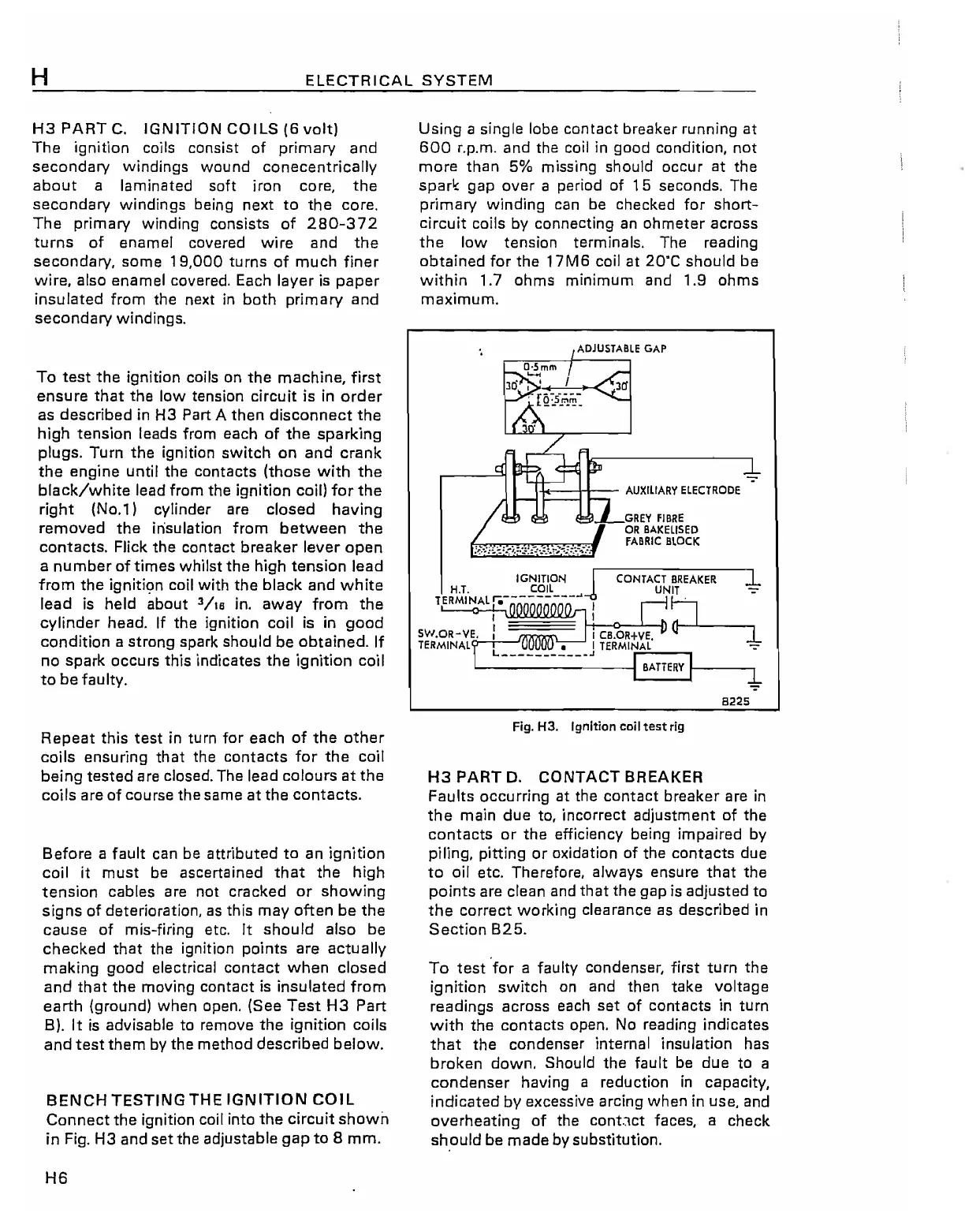
BENCH
TESTING
THE
IGNITION
COIL
Connect
the
ignition coil into
the
circuit
shown
in
Fig. H3 and set the adjustable
gap
to
8
mm.
H6
Using
a single lobe contact breaker running at
600
r.p.m. and the coil in good condition,
not
more
than 5% missing should occur at the
sparl< gap
over
a period of
15
seconds. The
primary
winding
can
be
checked
for
short-
circuit
coils
by
connecting
an
ohmeter
across
the
low
tension terminals. The reading
obtained
for
the
17M6
coil at
20'C
should be
within
1.7 ohms
minimum
and 1.9
ohms
maximum.
I.J<--++--
AUXILIARY
ELECTRODE
=~_:GREY
FIBRE
OR
BAKEllSED
FABRIC
BLOCK
IGNITION 1
CONTACT
BREAKER
'1
H.T.
COIL
UNIT _
TERMINAlr;---------
...
I
~
~
~I
5W.OR-VE.
I I CB.OR+VE,
TERMINAL
L
~
__
J
TERMINAL
7
BATTERY
8225
Fig.
H3. Ignition coil
test
rig
H3
PART
D.
CONTACT
BREAKER
Faults occurring at the
contact
breaker are in
the
main
due
to, incorrect adjustment
of
the
contacts
or
the
efficiency being impaired by
piling,
pitting
or
oxidation
of
the contacts due
to
oil etc. Therefore, always ensure
that
the
points
are clean and
that
the gap is adjusted
to
the
correct
working
clearance
as
described in
Section
B25.
To
test
'for
a faulty condenser,
first
turn
the
ignition
switch
on
and then take voltage
readings across each set
of
contacts in
turn
with
the
contacts
open. No reading indicates
that
the
condenser internal insulation has
broken
down.
Should the
fault
be
due
to
a
condenser
having a reduction
in
capacity,
indicated
by
excessive arcing when in use, and
overheating
of
the con!.]ct faces, a check
should
be
made
by substitution.