C
PRIMARY
DRIVE
adjuster C inwards until
the
correct
chain slackness
Is
obtained.
Re-tlghten
the
self-locking
nut
B.
Note
that
the
washer D incorporates a special oil seal
which
must
be
renewed
In
the
event
of
leakage.
It is
most
important
that
the
chain
should
not
be
tight.
When
adjustment
is
completed, replace
the
slotted
Inspection plug.
SECTION C5
TO
ItEMOVE
AND
REPLACE
THE
OUTER
PRIMARY
CHAINCASE
COVER
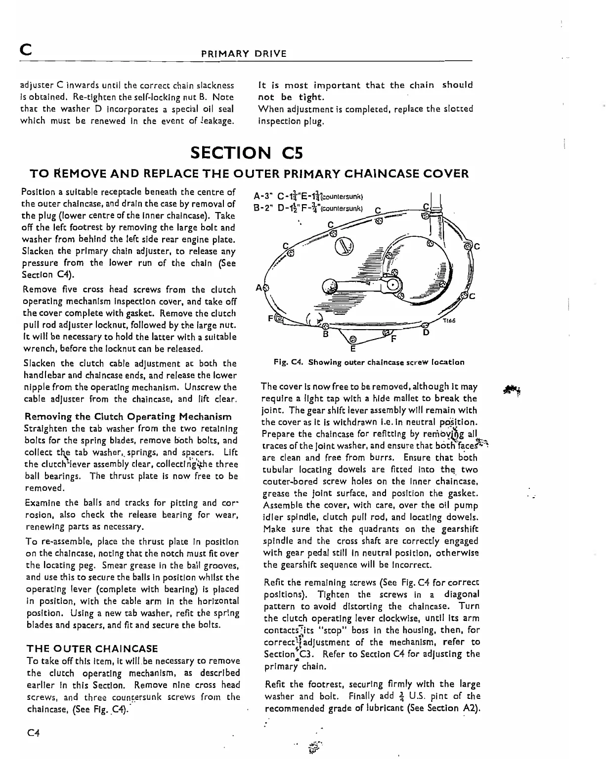
Fig. C4.
Showing
outer
chalncase
screw
location
,,166
D
F
'.
The
cover
Is
now
free
to
be
removed,
although
It
may
require
a light
tap
with a hide mallet
to
break
the
Joint.
The
gear
shift lever assembly will
remain
with
the
cover
as It
Is
withdrawn
I.e.
In
neutral pc:s\tlon.
Prepare
the
chaincase for refitting
by
reniby~g
ail _
traces
of
the
Joint washer, and
ensure
that
boch
face1i:-,
are
clean and free from
burrs.
Ensure
that
b~th
tubular
locating dowels
are
fitted Into
th~.
two
couter~bored
screw holes on the Inner chaincase.
grease
the
joint
surface, and position
the
gasket.
Assemble
the
cover, with care,
over
the
011
pump
Idler
spindle, clutch pull
rod,
and locating
dowels.
Make
sure
that
the
quadrants on
the
gearshift
spindle
and
the
cross shaft
are
correctly
engaged
with
gear
pedal still
In
neutral position,
ocherwlse
the
gearshift
sequence
will be Incorrect.
Refit
the
remaining screws (See
Fig.
C4
for
correct
positions). Tighten
the
screws
In
a diagonal
pattern
to
avoid distorting
the
chalncase.
Turn
the
clutch
operating
lever clockwise, until Its
arm
contacts:its "stop" boss
in
the housing.
then.
for
correctl!adjustment
of
the
",echanlsm,
refer
to
~
Sectlon.C3.
Refer
to
Section
C4
for
adjusting
the
primary
chain.
Refit
the
footrest,
securing firmly
with
the
large
washer
and bolt. Finally add
~
U.s.
pint
of
the
recommended
grade
of
lubricant
(See
Section
A2).
A
A-3" C-1l'"E-1i!1counte"unkl
B 2
" 0 1'''F 3."
..
..
2 .....
(countersunk)
C
_-=---5Ji:3.
:;;..--
C~@
.......-
........
@ 0
:r-
~
~~_
.' t
THE
OUTER
CHAINCASE
To
take
off this Item,
It
wlll.be necessary
to
remove
the
clutch
operating
mechanism,
as
described
earlier
In
this
Section. Remove nine cross head
screws,
and
three
coun~.ersunk
screWs from
the
chalncase, (See Fig.
C4):
Position a suitable receptacle beneath
the
centre
of
che
outer
chaincase, and drain
the
case by removal
of
the
plug
(lower
centre
of
the
Inner chalncase).
Take
off
the
left
footrest
by removing
the
large
bolt
and
washer
from behind
the
left side
rear
engine plate.
Slacken
the
primary
chain adjuster,
to
release any
pressure
from
the
lower
run
of
the
chain (See
Section C4).
Remove
five cross head screws from
the
clutch
operating
mechanism Inspection cover, and
take
off
the
cover
complete
with gasket. Remove
the
clutch
pull rod
adjuster
locknut, followed by
the
large
nut.
It will be necessary
to
hold
the
latter
with
a suitable
wrench,
before
the
locknut can be released.
Slacken
the
clutch cable
adjustment
at
both
the
handlebar
and chalncase ends, and release
the
lower
nipple from
the
operating mechanism.
Unscrew
the
cable
adjuster
from the chalncase, and lift clear.
Removing
the
Clutch
Operating
Mechanism
Straighten
the
tab washer from
the
two
retaining
bolts
for
the
spring blades,
remove
both
bolts, and
collect
th.t' tab washer,_ springs, and
sp,~~ers.
Lift
the
c1utch~lever
assembly clear,
collectlng"he
three
ball bearings.
The
thrust
plate
Is
now
free
to
be
removed.
'-.
Examine
the
balls
and
tracks for
pitting
and
cor-
rosion, also check the release bearing for wear,
renewing
parts as necessary.
To
re-assemble, place the
thrust
plate
In
position
on
the
chalncase. noting that
the
notch must
fit
over
the
locating peg. Smear grease
In
the
ball grooves,
and use this
to
secure
the
balls
In
position whilst
the
operating
lever
(complete with bearing)
Is
placed
In
position,
with
the
cable arm
In
the
horizontal
position.
Using a new tab washer, refit
the
spring
blades and spacers, and fit and
secure
the
bolts.
C4
: