ELECTRICAL SYSTEM
H
(2) Connect a
D.C.
voltmeter
(0-1
5VI
across
the battery
terminals
and an
ammeter
(0-10
ampl
between
the
battery
negative
and the free
ends
of
the
wire resistance,
using a crocodile clip
to
make the
connection.
(3) Move the clip along
the
wires, making
contact
with
both
wires until the
ammeter
reading
is
numerically equal to
the
number
of
volts
indicated
on
the
volt-
meter. The
resistance
is
then
1 ohm. Cut
the wire
at
this point,
twist
the
two
ends
together
and
wind
the
wire on an
asbestos
former
approximately
2 inches
15
em.) dia.
so
that
each
turn
does
not
contact
the
one
next
to
it.
SECTION
H6
ZENER
DIODE
CHARGE
CONTROL
DESCRIPTION
The Zener Diode
output
regulating
system
uses
all
the coils
of
the
6-coil alternator
connected
permanently
across
the
rectifier,
provides automatic control for
the
charging
current.
It
will
only
operate
successfully where
it
is
connected
in
parallel with
the
battery
as
shown
in
the wiring diagram (Section
H20
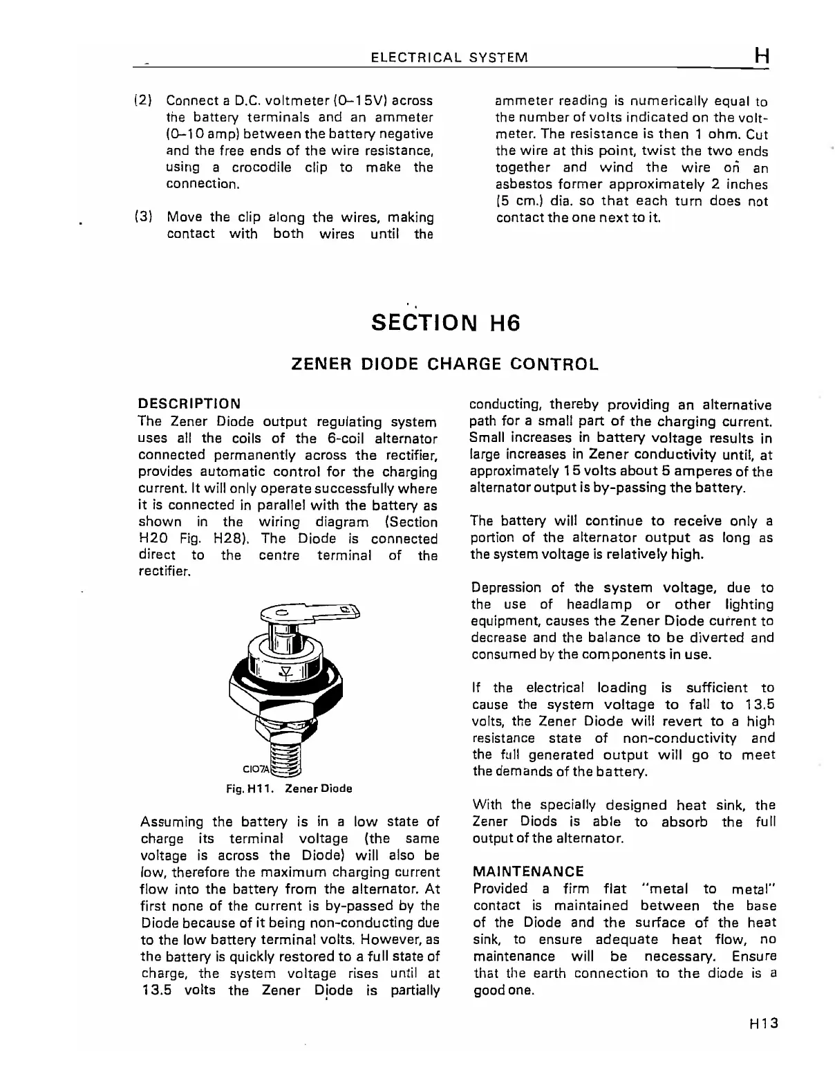
Fig.
H28).
The
Diode
is
connected
direct to the
centre
terminal of the
rectifier.
Assuming the battery is
in
a low
state
of
charge its terminal
voltage
(the
same
voltage
is
across
the
Diode) will also be
low, therefore the maximum charging current
flow into
the
battery from
the
alternator. At
first none of the
current
is
by-passed
by
the
Diode
because
of it being non-conducting due
to
the low battery terminal volts. However, as
the
battery
is
quickly
restored
to
a full
state
of
charge,
the
system
voitage rises until
at
13.5
volts
the
Zener
Diode is partially
conducting,
thereby
providing
an
alternative
path for a small part
of
the
charging
current.
Small increases
in
battery
voltage
results
in
large increases
in
Zener
conductivity
until,
at
approximately
15
volts
about
5
amperes
of
the
alternator
output
is
by-passing
the
battery.
The battery will
continue
to
receive only a
portion of
the
alternator
output
as
long
as
the system voltage
is
relatively high.
Depression of the
system
voltage,
due
to
the use of
headlamp
or
other
lighting
equipment,
causes
the
Zener
Diode
current
to
decrease and the
balance
to
be
diverted and
consumed by
the
components
in
use.
If
the electrical loading is sufficient
to
cause the
system
voltage
to
fall
to
13.5
volts, the
Zener
Diode will
revert
to
a high
resistance
state
of
non-conductivity
and
the
full
generated
output
will
go
to
meet
the demands of the
battery.
With the specially
designed
heat
sink, the
Zener Diods
is
able
to
absorb
the
full
output
ofthe
alternator.
MAINTENANCE
Provided a firm
flat
"metal
to
metal"
contact
is
maintained
between
the
base
of the Diode and
the
surface
of
the
heat
sink, to ensure
adequate
heat
flow, no
maintenance will
be
necessary.
Ensure
that the earth
connection
to
the
diode
is
a
good one.
H13