8
ENGINE
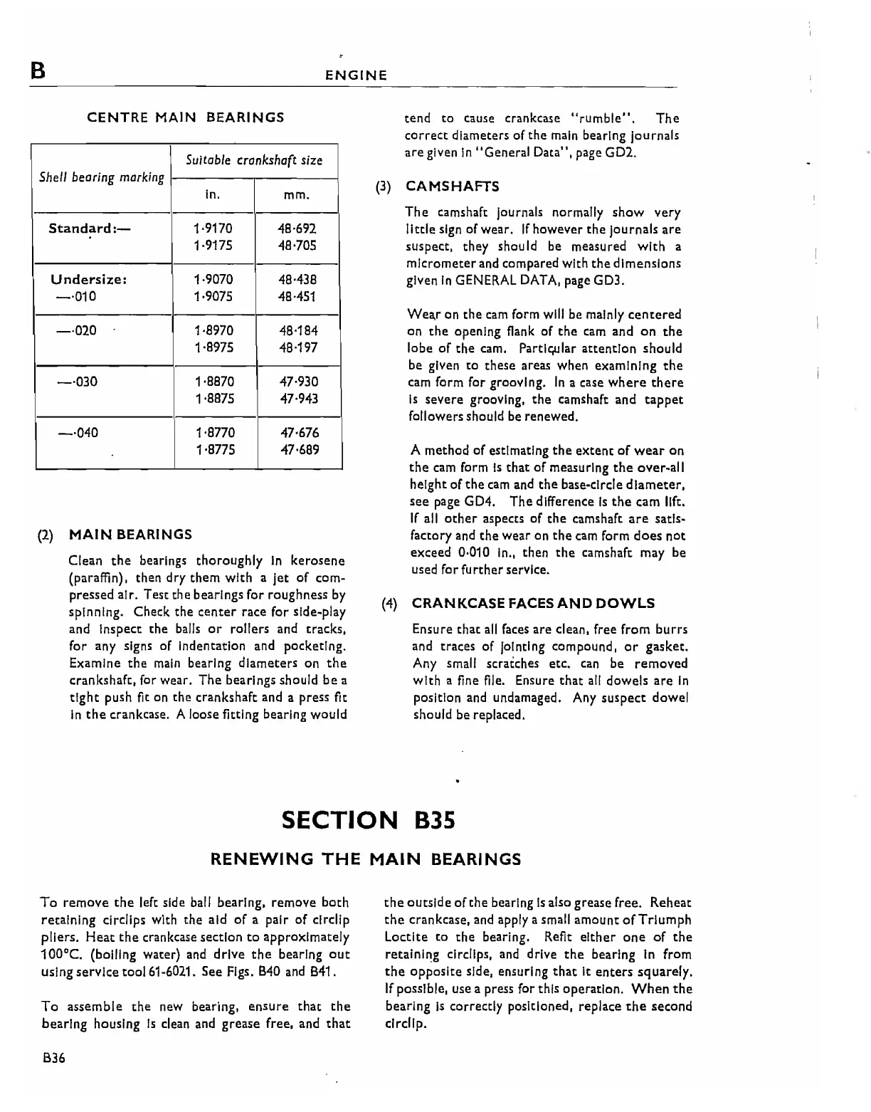
CENTRE
MAIN
BEARINGS
Suitable crankshaft size
Sheil bearing marking
in.
mm.
standard:-
1-9170 48·692
1·9175
48-705
Undersize:
1-9070
48·438
-·010
1-9075
48·451
-·020
1·8970 48·184
1·8975 48·197
-·030
1·8870
47·930
1·8875 47·943
-·040
1·8770
47·676
1·8775 47·689
(2)
MAIN
BEARINGS
Clean
the
bearings thoroughly
In
kerosene
(paraffin), then dry them with a Jet
of
com-
pressed air. Test the bearings for roughness
by
spinning. Check the
center
race for side-play
and inspect the balls
or
rollers and tracks,
for any signs of Indentation and pocketing.
Examine
the
main
bearing
diameters
on
the
crankshaft, for wear.
The
bearings should
be
a
tight
push fit on the crankshaft and a press fit
in
the
crankcase. A loose fitting bearing would
tend
to
cause crankcase
"rumble".
The
correct
diameters
of
the
main
bearing journals
are given
In
"General Data",
page
GD2.
(3)
CAMSHAFTS
The
camshaft Journals normally
show
very
little
sign of wear.
If
however
the
Journals
are
suspect, they should be measured
with
a
micrometer and compared with
the
dimensions
given
In
GENERAL
DATA,
page GD3.
Wea,r on the cam form will be mainly
centered
on
the
opening flank of
the
cam and
on
the
lobe
of
the cam. Partic;ular
attention
should
be given
to
these areas when examining
the
cam form for grooving.
In
a case
where
there
is
severe grooving,
the
camshaft and
tappet
followers should be renewed.
A method of estimating
the
extent
of
wear
on
the
cam form
Is
that
of measuring
the
over-all
height of
the
cam
and
the
base-circle
diameter,
see
page GD4.
The
difference
Is
the
cam
11ft.
If
all
other
aspects of
the
camshaft
are
satis-
factory and
the
wear on
the
cam
form
does
not
exceed 0·010
In.,
then
the
camshaft may be
used for
fu
rther
service.
(4)
CRANKCASE
FACES
AND
DOWLs
Ensure that all faces are clean, free from burrs
and traces of jointing compound,
or
gasket.
Any small scraiches etc.
can
be removed
with
a fine file. Ensure
that
all
dowels
are
In
position and undamaged. Any suspect dowel
should be replaced.
SECTION 835
RENEWING
THE
MAIN
BEARINGS
To
remove
the
left side ball bearing, remove both
retaining clrclips with the aid
of
a pair
of
circllp
pliers.
Heat
the
crankcase section
to
approximately
100'C.
(boiling water) and drive
the
bearing
out
using service tool 61-6021. See Figs.
B40
and B41.
To
assemble
the
neW
bearing,
ensure
that
the
bearing housing
is
dean and grease free, and
that
B36
the
outside
of
the
bearing
is
also grease free. Reheat
the
crankcase, and apply a small amount
of
Triumph
Loctlte
to
the
bearing. Refit
either
one
of
the
retaining circlips, and drive
the
bearing in from
the
oppOSite side, ensuring
that
it
enters
squarely.
If
possible, use a press for this operation.
When
the
bearing
is
correctly positioned, replace
the
second
drcllp.