TRANSMISSION
(GEARBOX)
SECTION
DI
SEQUENCE
OF
GEARSHIFTING
D
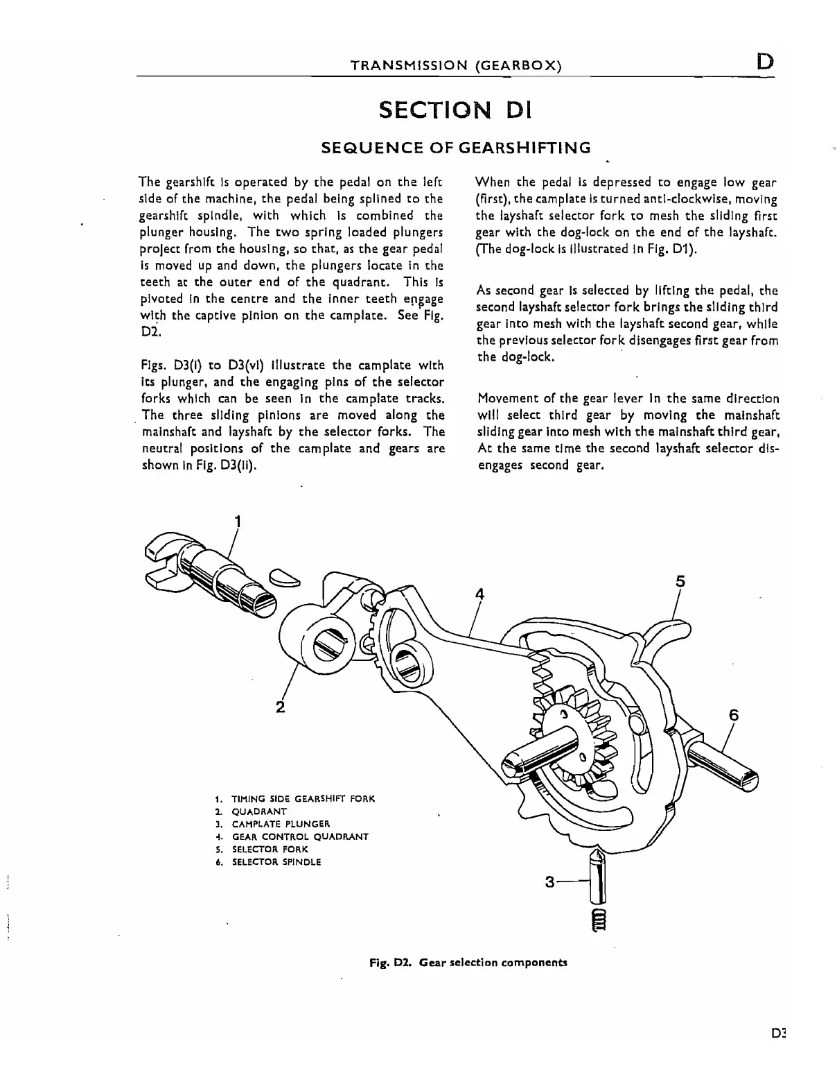
The gearshift
Is
operated
by
the
pedal
on
the
left
side of the machine,
the
pedal being spllned
to
the
gearshift spindle, with which
Is
combined the
plunger housing.
The
two
spring loaded plungers
project from
the
housl ng,
so
that,
as
the
gear
pedal
Is
moved
up
and down,
the
plungers locate
In
the
teeth
at
the
outer
end of
the
quadrant.
This
Is
pivoted
In
the
centre
and
the
Inner
teeth
e~~age
with the captive pinion
on
the
camplate. See
Fig.
D2.
Figs.
D3(1)
to
D3(vi) Illustrate
the
camplate with
Its plunger, and
the
engaging pins
of
the
selector
forks which can be
seen
In
the
camplate tracks.
. The
three
sliding pinions
are
moved along
the
malnshaft and layshaft by
the
selector
forks. The
neutral positions
of
the
cam plate and gears
are
shown
In
Fig.
D3(1I).
1
2
1. TIMING
SiDE
GEARSHIFT FORK
1.
QUADRANT
J.
CAHPLATE
PLUNGER
... GEAR CONTR.OL
QUADRANT
S.
SELECTOR
FORK
6.
SELeCTOR.
SPINDLE
When
the
pedal
Is
depressed
to
engage low gear
(first),
the
camplate
Is
turned
anti-clockwise, moving
the
layshaft selector fork
to
mesh
the
sliding first
gear with the dog-lock on
the
end of
the
layshaft.
(The dog-lock
Is
Illustrated
In
Fig. D1).
As
second gear
is
selected
by
lifting
the
pedal,
the
second layshaft selector
fork
brings
the
sliding
third
gear Into mesh with
the
layshaft second gear, while
the
previous selector
fork
disengages first
gear
from
the
dog-lock. .
Movement of the gear lever
In
the
same direction
will select
third
gear by moving
the
malnshaft
sliding gear Into mesh
with
the
malnshaft
third
gear,
At
the
same time
the
second layshaft
selector
dis-
engages second gear.
5
Fig. D2. Gear selection components
D3