H
ElECTRICAL
SYSTEM
SECTION
H2
CONDENSER
PACK
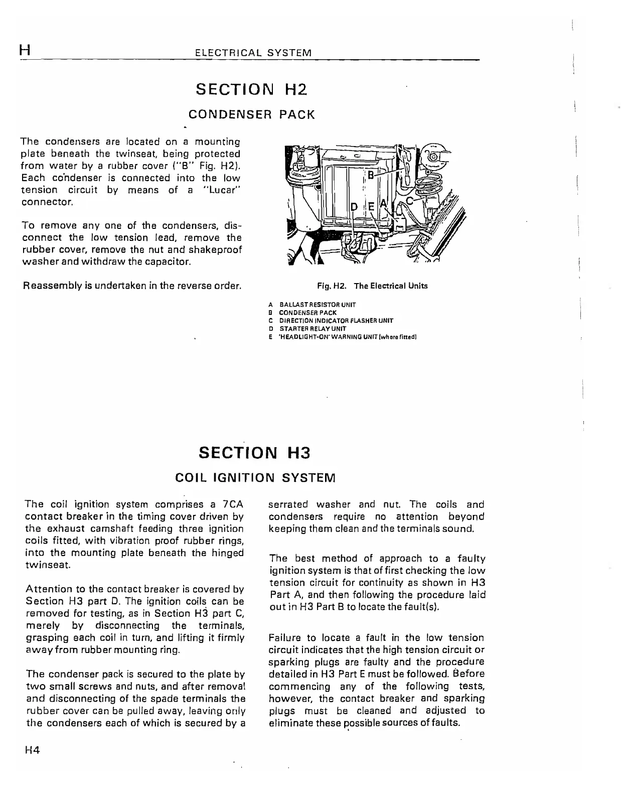
The
condensers are located on a
mounting
plate
beneath the twinseat, being
protected
from
water
by
a rubber cover
("8"
Fig. H2).
Each co'ndenser is connected
into
the
low
tension
circuit
by means
of
a
"Lucar"
connector.
To
remove
anyone
of
the condensers,
dis-
connect
the
low
tension lead, remove
the
rubber
cover, remove the
nut
and
shakeproof
washer
and
withdraw
the capacitor.
Reassembly
is undertaken in
the
reverse order. Fig. H2. The Electrical Units
A BALLAST RESISTOR UNIT
8 CONDENSER
PACK
C DIRECTION INDiCATOR
FLASHER
UNIT
o
STARTER
AEIAYUNIT
E 'HEADLIGHT-ON' WARNING UNtT(whllrafittl!!d]
SECTION
H3
COIL
IGNITION
SYSTEM
The
coil ignition system comprises a
7CA
contact
breaker
in the timing
cover
driven by
the
exhau3t camshaft feeding three ignition
coils
fitted,
with
vibration
proof
rubber rings,
into
the
mounting
plate beneath the hinged
twinseat.
A
ttention
to
the contact breaker
is
covered by
Section
H3
part
D.
The ignition coils can be
removed
for
testing,
as
in
Section
H3
part
C,
merely
by
disconnecting
the
terminals,
grasping
each coil in turn, and
lifting
it
firmly
away
from
rubber mounting ring.
The
condenser
pack
is
secured
to
the plate
by
two
small
screws and nuts, and
after
removal
and
disconnecting
of
the spade
term
inals
the
rubber
cover
can
be
pUlled away, leaving
only
the
condensers each
of
which
is
secured
by
a
H4
serrated
washer and nut. The coils and
condensers require no attention
beyond
keeping them clean
and
the terminals sound.
The
best method
of
approach
to
a
faulty
ignition
system
is
that
of
first
checking
the
low
tension
circuit
for
continuity
as
shown
in
H3
Part
A,
and then following the procedure laid
out
in
H3 Part 8 to locate the fault!s).
Failure
to
locate a fault
in
the
low
tension
circuit
indicates
that
the high tension
circuit
or
sparking
plugs
are
faulty and the
procedure
detailed
in H3 Part Emust be followed.
Before
commencing
any
of
the
following
tests,
however,
the
contact breaker and
sparking
plugs
must be cleaned and adjusted
to
eliminate
these
~ossible
sources
offaults.