E
FRAME
SECTION
EI2
FRAME
ALIGNMENT
fi~n========{f==:~
3/
4
"DIA.
~
16thd.
UNF
5/
S
'DIA.
5/
S
'DIA.
[
Ii
'7500"
n]
~
'749S"D1A.
-_-f,j
~
~,-DI_A'
1811
0 B
.I
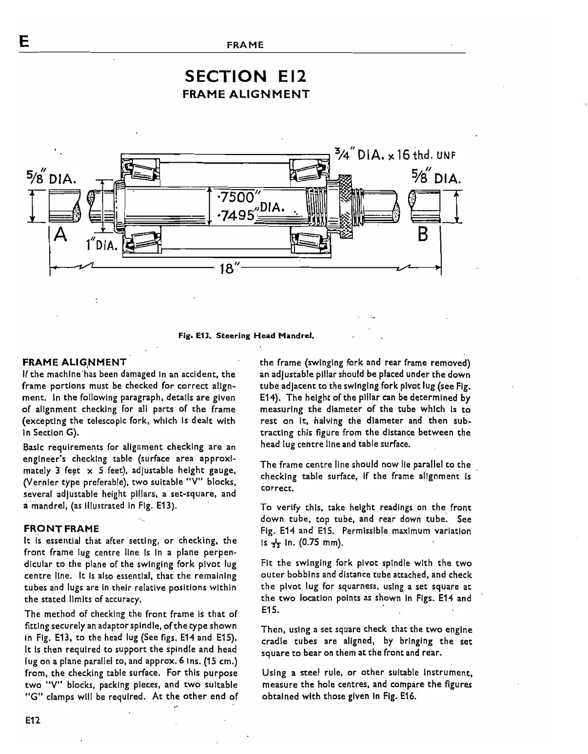
Fig. E13. Steer-log
Head
Mandrel.
FRAME
ALIG,NMENT
If
the
machine'has been damaged
In
an
accident.
the
frame portions must
be
checked for
correct
align-
ment.
In
the
following paragraph, details
are
given
of
alignment checking for
all
parts
of
the
frame
(excepting
the
telescopic fork, which
Is
dealt
with
In Section G).
Basic requirements for alignment checking
are
an
engineer's
checking table (surface
area
approxI-
mately 3
fe~t
x 5 feet), adjustable height gauge.
(Vernier type preferable), two suitable
"V"
blocks.
several adjustable height pillars, a set-square, and
a'mandrel,
(as illustrated
In
Fig.
E13).
FRONT
FRAME
It
Is
essential
that
after setting,
or
checking,
the
front
frame lug centre line
Is
In
a plane
perpen-
dicular
to
the
plane of the swinging fork
pivot
lug
centre
line. It
Is
also essential,
that
the
remaining
tubes
and lugs are
Inthelr
relative positions within
the
stated limits of accuracy.
The
method of checking
the
front
frame
Is
that
of
fitting securely
an
adaptorspindle,
of
the
type
shown
In
Fig.
E13,
to
the head
lug
(See figs.
E14
and E15).
It
Is
then
required to support
the
spindle and head
lug on a plane parallel to, and approx. 6 Ins.
(15
em.)
from,
the
checking table surface. For
this
purpose
two
"V" blocks, packing pieces, and
two
suitable
"G"
ciamps will
be
required.
At
the
other
end
of
E12
the
frame (swinging fork and
rear
frame removed)
an adjustable pillar should be placed under
the
down
cube adjacent
to
the
swinging fork pivot lug (see
Fig.
E14).
The
height of the pillar
can
be
determined
by
measuring
the
diameter
of
the
tube which
Is
to
rest
on It, halving the
diameter
and
then
sub-
tracting
this figure from
the
distance
between
the
head lug
centre
line and table surface.
The
frame
centre
line should now
lie
parallel
to
the
checking table surface,
If
the
frame alignment
Is
correct.
To
verify this, take height readings on
the
front
down
tube,
top tube, and
rear
down
tube:
See
Fig.
E14
and
E15.
Permissible maximum variation
Is
-n
In.
(0.75
mm).
Fit
the
swinging fork pivot spindle with
the
two
outer
bobbins and distance
tube
attached, and check
the
pivot lug for squarness, using a
set
square
at
the
two
location points
as
shown
In
Figs.
E14
and
E15. '
Then,
using a
set
square check that
the
two
engine
cradle
tubes
are aligned,
by
bringing
the
set
square
to
bear
on them
at
the
front and
rear.
Using a steel rule,
or
other
suitable
Instrument,
measure
the
hole centres, and compare
the
figures
obtained
with
those given
In
Fig.
E16.
I.!