LUBRICATION
SYSTEM
A
To
prevent
the
loss-of all from
the
oll.cooler and all
tank the ends of
the
pipes should be plugged
as
they
are disconnected.
When the valve has been
removed
t.he hexagonal
domed
cap
can be unscrewed from
the
main body,
thus releasing
the
piston which should be with-
drawn.
Thoroughly clean
all
parts
in
(kerosene) paraffin and
Inspect for wear.
If
any defect
is
apparent, e.g.
scoring
of
piston, spring fracture, etc.
the
whole
unit must be replaced.
When
screwing
the
relief
valve unit into the crankcase,
fit
a new fibre washer
between
the
body and
the
crankcase. (Figure
AS).
SECTION
A7
REMOVING
AND
REPLACING
THE
OIL
PUMP
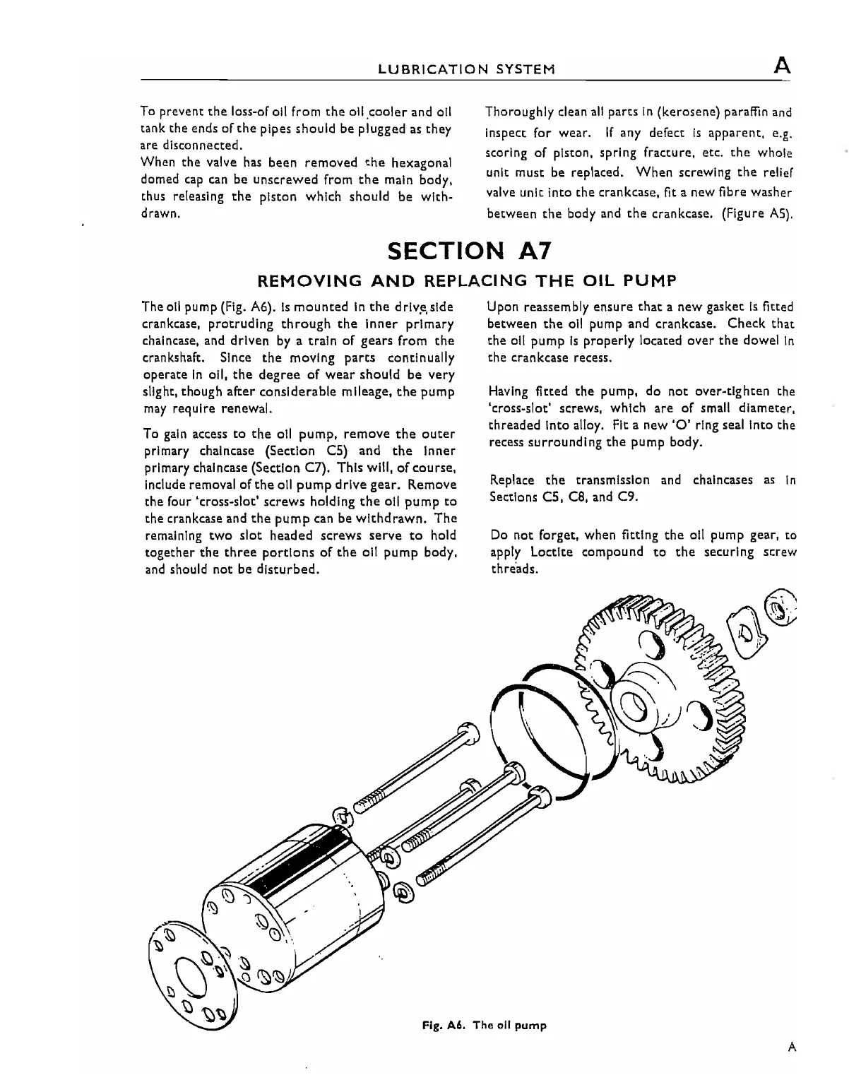
Theall pump (Fig. A6).
is
mounted
In
the
drlv.e,slde
crankcase,
protruding
through
the
Inner
primary
chalncase, and driven
by
a
train
of
gears from
the
crankshaft. Since
the
moving
parts
continually
operate
In
all,
the
degree
of
wear
should be very
slight, though after considerable mileage.
the
pump
may
require renewal.
To
gain
access
to the
011
pump, remove
the
outer
primary chalncase (Section
CS)
and
the
Inner
primary chalncase (Section C7). This will,
of
course,
Include removal of
the
oil
pump
drive gear. Remove
the four 'cross-slot' screws holding
the
oil pump
to
the crankcase and
the
pump
can be
withdrawn.
The
remaining
two
slot
headed screws
serve
to
hold
together
the
three
portions
of
the
011
pump
body,
and
should not be
disturbed.
Upon reassembly ensure
that
a new gasket
is
fitted
between
the
oil pump and crankcase. Check that
the
011
pump
Is
properly located
over
the
dowel
In
the crankcase recess.
Having fitted
the
pump, do
not
over-tighten the
Icross~slot'
screws, which are
of
small diameter,
threaded into alloy. Fit a new
'0'
ring seal into the
recess
surrounding
the
pump body.
Replace
the
transmission and chalncases
as
In
Sections C5,
ca,
and C9.
Do
not forget, when fitting
the
all pump gear, to
apply Loctlte compound
to
the
securing screw
threads.
Fig. A6. The all
pump
A9