B
ENGINE
SECTION
B24
REMOVING
AND
REPLACING
THE
CONTACT
BREAKER
The
contact
breaker
Is
housed
In
the
timing
cover
on
ti~e
right
side
of
the
engine, and
Is
driven
by
the
ex~aust
camshaft. It consists
of
three
sets
of
points
(one
for
each cylinder) and a fully
automatic
centrifugal
typlO
spark advance and
retard
mecha-
nism.
Th~
working
parts are
protected
by
a circular
cover
and
gasket.
A seal
is
provided
In
the
back
of
the
housing
to
prevent
the
ingress
of
oil from
the
timing
chest.
The
contact
breaker
plate
is
secured
by
three
plliar bolts
to
the
housing and
the
auto
advance
mechanism fits Into
the
tapered
hole
in
the
end
of
the
exhaust
camshaft.
To
remove
the
contact
breaker
assembly, first
disconnect
the
battery
feed terminal
at
the
fuse
holder.
Remove
the
three
screws and
withdraw
the
chromium
plated cover and gasket. Remove
the
centre
boit
and
screw
in
service tool 61-07B2 until
the
auto
advance cam
is
released from Its locking
taper
in
the
camshaft. A sharp tap on
the
free
end
of
the
wrench
will assist
In
disconnecting
the
taper
Joint.
Unscrew
the
tool and remove
three
plliar
bolts
and plain washers from
the
contact
breaker
plate. Both
the
plate and auto advance can
then
be
removed.
To
detach
the
contact
breaker
completely, it will be
necessary
to
disconnect the three leads at
the
snap
connectors
terminals behind
the
styling
cover
so
that
the
leads
can
be withdrawn
through
the
grommet
In
the
timing case.
Prior
to
refitting the spark advance and
retard
unit
it
Is
advisable
to
add a small amount of oil
to
the
pivot pins. (Refer to Section A11). The
unit
should
be
refitted into
the
camshaft taper, and
the
bolt
refitted
without
tightening. The base plate
should
be repositioned so
that
the
set
of
points
with
the
Red/Black lead
Is
to
the
the
rear
of
the
engine.
Replace
the
pillar bolts and plain washers.
Adjust
the
C.B. points (Section
B2S).
Reset
th~'
spark timing (Section
B26).
When
the
correct
setting
is
achieved
for
all
cylinders ensure that the contact breaker
screws
are
tight,
then
refit
the
cover and gasket.
I
MPORTANT
NOTE:
"Run-out"
on
the
con-
tact
breaker
cam,
or
misalignment
of
the
secondary
backplate
centre
hole,
can
result
in
contact
between
the
cam
and
backplate.
This
can
result
in
the
auto
advance
remaining
in
the
retarded position. To check for "run-out
u
•
measure
the
points
gap
with
the
contact
nylon
heel
aligned
with
the
cam
scribe
mark
for
each
set
of
joints.
Should
there
be
a
discrepancy
greater
then
0·003
in.,
tap
the
outer
edge
ofthe
cam
with
a
brass
drift
(with
the
cam
securing
bolt
remaining
tight.
In
cases
of
misalignment
of
the
secondary
backplate
hole,
check
the
cam
clearance
in
different
positions,
and
elongate
the
hole
only
where
the
backplate
rubs
the
cam.
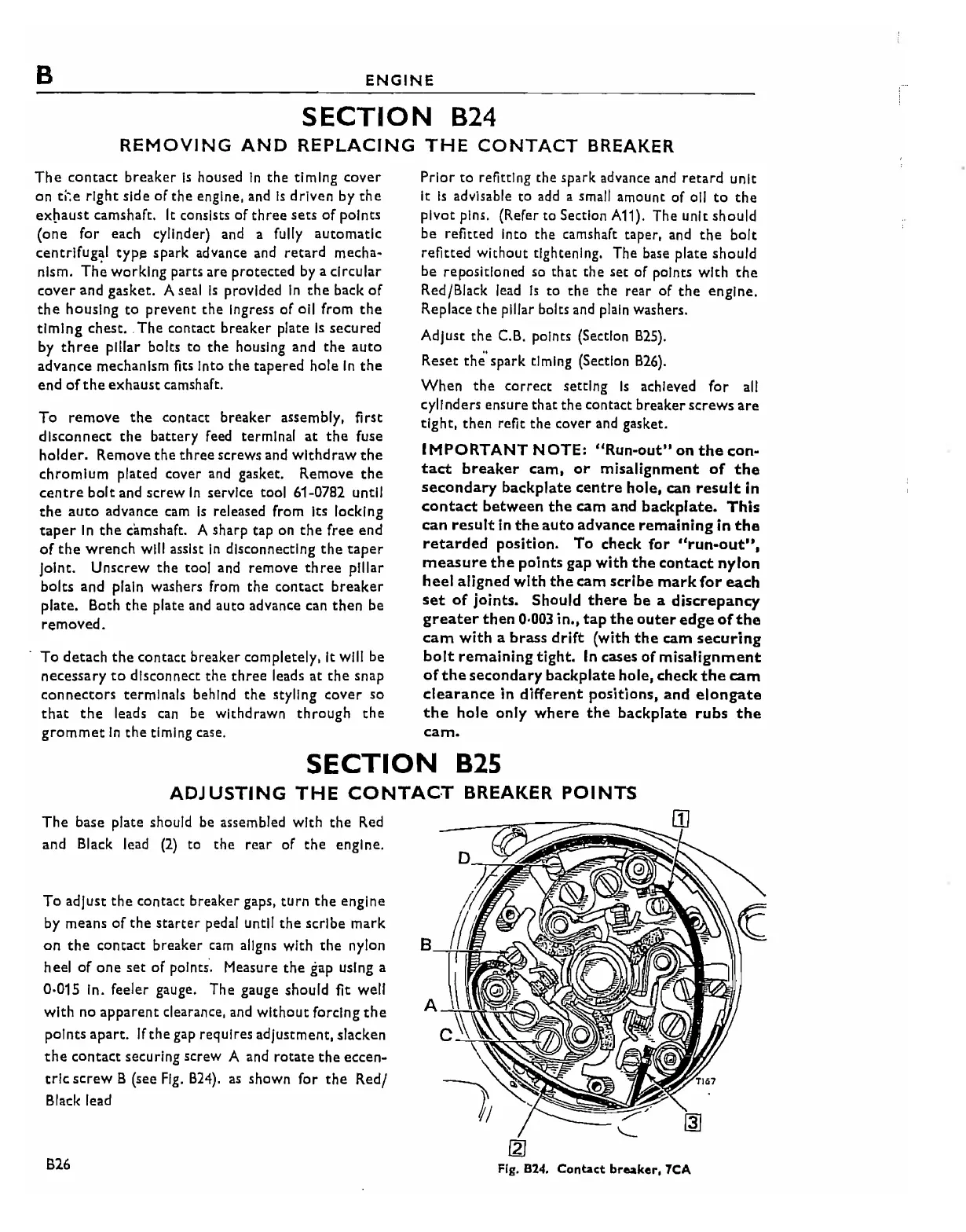
The
base plate should be assembled
with
the
Red
and Black lead
(2)
to
the
rear
of
the
engine.
To
adjust
the
contact
breaker
gaps,
turn
the
engine
by means
of
the
starter
pedal until
the
scribe
mark
on
the
contact
breaker
cam
aligns with
the
nylon 8
heel
of
one
set
of
points. Measure
the
gap using a
0·015 in. feeler gauge. The gauge should fit well
with
no
apparent
clearance, and
without
forcing
the
points
apart.
If
the
gap requires adjustment, slacken
the
contact securing
screW
A
and
rotate the eccen-
tric
screw
B (see
Fig.
B24).
as
shown
for
the
Red/
Black lead
B26
fZ]
Fig.
824. Contact breaker.
7CA