B
ENGINE
SECTION
B6
REMOVING
AND
REPLACING
THE
AIR
FILTER
The
common air filter unit has
rubber
grommets
which fit
over
plain sleeves on
the
carburetor
Intakes
to
provide airtight joints and these
grom-
mets
must
be
In
good condition for
the
filter
to
be
effective
..
The whole assembly
Is
secured
to
the
carburetor
adaptor
by
means
of
two
bolts and
locknuts,
the
main nuts being Inside, and
part
of,
the
filter box.
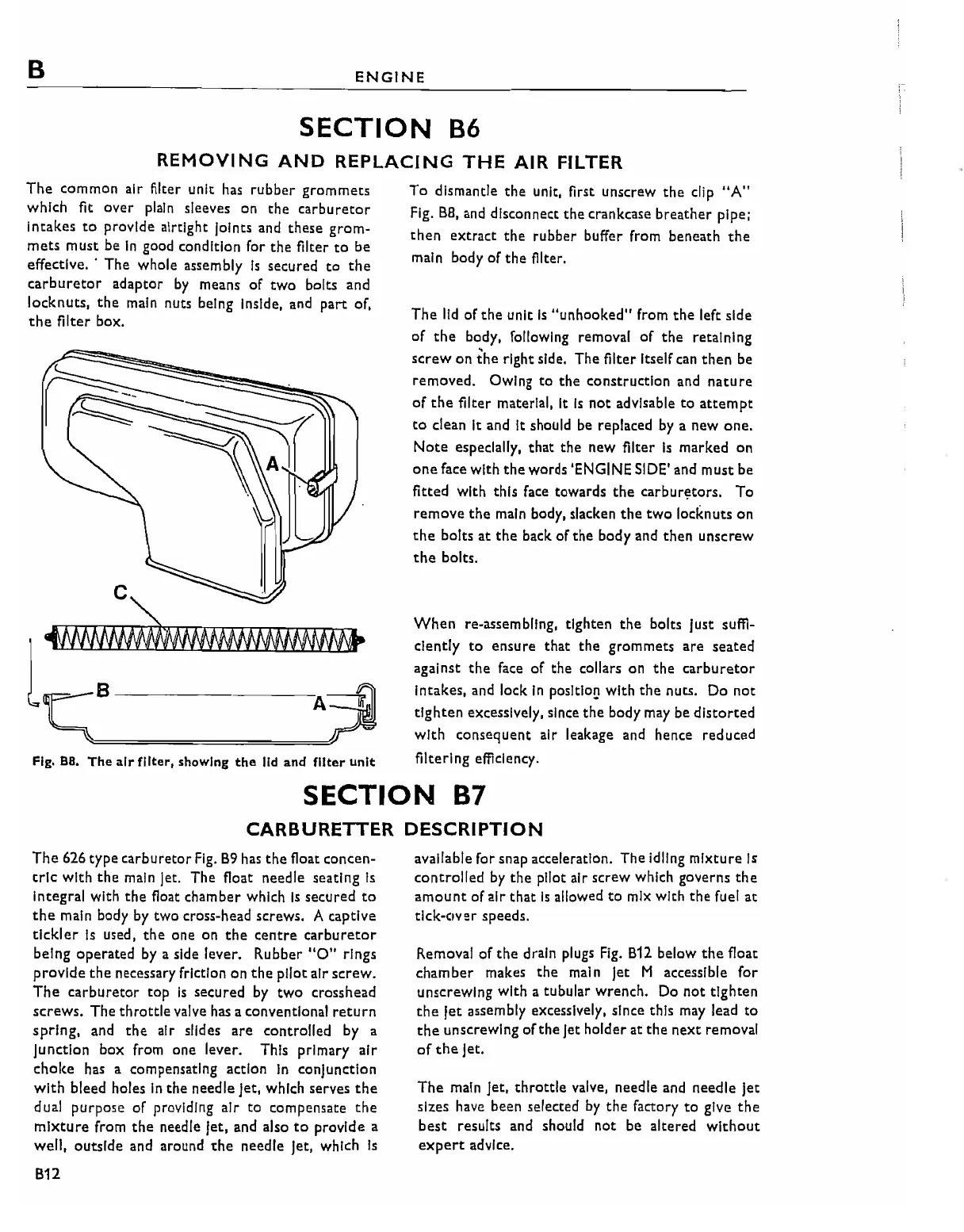
Fig.
B8.
The airfilter, showing
the
lid
and filter unit
To
dismantle
the
unit, first unscrew
the
clip
"A"
Fig.
B8,
and disconnect
the
crankcase
breather
pipe;
then
extract
the
rubber buffer from beneath
the
main body
of
the
fllter.
The
lid
of
the
unit
Is
"unhooked"
from
the
left side
of
the
body, following removal
of
the
retaining
screw
on
the
right side. The fllter Itself can
then
be
removed. Owing
to
the construction
and
nature
of
the
filter material, It
Is
not
advisable
to
attempt
to
clean It and It should be replaced
by
a new
one.
Note
especially,
that
the
new filter
Is
marked
on
one
face with
the
words 'ENGINE SIDE' and must
be
fitted with this face towards
the
carbur~tors.
To
remove
the
main body, slacken
the
two
locknuts
on
the
bolts
at
the
back
of
the
body and then unscrew
the
bolts.
When
re-assembling, tighten
the
bolts Just suffi-
ciently
to
ensure
that
the
grommets
are
seated
against
the
face
of
the
collars
on
the
carburetor
Intakes, and lock
In
posltlo~
with
the
nuts. Do
not
tighten
excessively, since
the
body may be
distorted
with
consequent air leakage and hence reduced
filtering efficiency.
SECTION
87
CARBURETTER
DESCRIPTION
The
626 type
carburetor
Fig.
B9
has
the
float concen-
tric
with
the
main Jet. The float needle seating
Is
Integral with
the
float chamber which
Is
secured
to
the
main body
by
two cross-head screws. A captive
tickler
Is
used,
the
one on
the
centre
carburetor
being
operated
by
a side lever. Rubber
"0"
rings
provide
the
necessary friction on
the
pilot air
screw.
The
carburetor
top
Is
secured by
two
crosshead
screws.
The
throttle
valve
has
a conventional
return
spring,
and
the
air slides
are
controlled by a
Junction
box
from one lever. This primary
air
cholte has a compensating action
in
conjunction
with
bleed holes
In
the
needle Jet, which serves
the
dual purpose
of
providing
air
to
compensate
the
mixture
from
the
needle Jet, and also
to
provide a
well, outside and around
the
needle Jet, which
Is
B12
available for snap acceleration. The Idling
mixture
Is
controlled
by
the
pilot air screw which governs
the
amount
of
air
that
Is
allowed
to
mix with
the
fuel
at
tlck-tlVer speeds.
Removal
of
the
drain plugs
Fig.
B12
below
the
float
chamber
makes
the
main Jet M accessible
for
unscrewing with a tubular wrench. Do
not
tighten
the
Jet
assembly excessively, since this may lead
to
the
unscrewing
of
the
Jet holder at
the
next
removal
of
the
Jet.
The
main Jet,
throttle
valve, needle and needle Jet
sizes have been selected
by
the
factory
to
give
the
best
results and should
not
be altered
without
expert
advice.