B
ENGINE
SECTION
88
REMOVING
AND
REPLACING
THE
CARBURETTERS
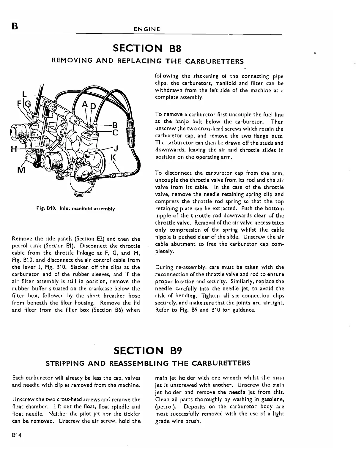
Fig. S10. Inlet manifold assembly
Remove
the
side panels (Section
E2)
and
then
the
petrol
tank
(Section
E1).
Disconnect
the
throttle
cable from
the
throttle
linkage
at
F,
G, and
M,
Fig. 810, and disconnect
the
air control cable from
the
lever
J,
Fig.
810. Slacken off
the
clips
at
the
carburetor
end
of the rubber sleeves,
and
If
the
air filter assembly
Is
stili
In
position, remove
the
rubber
buffer situated on
the
crankcase below
the
filter box, followed
by
the
short
breather
hose
from beneath
the
filter housing. Remove
the
lid
and filter from the filler box (Section 86)
when
following
the
slackening of
the
connecting pipe
clips,
the
carburetors, manifold and filter can be
withdrawn
from
the
left side of
the
machine
as
a
complete
assembly.
To remove a carburetor
first
uncouple the fuel line
at
the
banjo bolt below
the
carburetor.
Then
unscrew
~he
two cross-head screws which retain the
carburetor cap.
and
remove
the
two
flange nuts.
The
carburetor
can
then be drawn off
the
studs
and
downwards,
leaving
the
air and
throttle
slides
In
position on
the
operating arm.
To disconnect
the
carburetor
cap
from
the
arm,
uncouple
the
throttle
valve from Its rod and
the
air
valve from Its cable.
In
the
case
of
the
throttle
valve,
remove
the
needle retaining spring clip and
compress
the
throttle
rod spring so
that
the
top
retaining plate can be extracted. Push
the
bottom
nipple
of
the
throttle
rod downwards clear
of
the
throttle
valve. Removal of
the
air valve necessitates
only compression of the spring whilst
the
cable
nipple
Is
pushed clear
of
the
slide. Unscrew
the
air
cable abutment
to
free the carburetor cap
com~
pletely.
During re-assembly, care must be taken
with
the
reconnectlon
of
the
throttle valve
and
rod
to
ensure
proper
location and security. Similarly, replace
the
needle
carefully Into the needle let,
to
avoid
the
risk
of
bending. Tighten
all
six connection clips
securely, and make sure
that
the
lolnts
are
airtight.
Refer
to
Fig.
89 and 810 for gUidance.
SECTION
89
STRIPPING
AND
REASSEMBLING
THE
CARBURETTERS
Each
carburetor
will
already be less
the
cap, valves
and needle with
clip
as
removed from
the
machine.
Unscrew
the
two
cross-head screws
and
remove
the
float chamber.
Lift
out
the
float, float spindle and
float needle.
Neither
the pilot jet nor the
tickler
can
be
removed. Unscrew
the
air screw, hold
the
814
main
let
holder
with one wrench whilst
the
main
jet
is
unscrewed with another. Unscrew
the
main
let
holder
and remove
the
needle
jet
from
this.
Clean
all
parts thoroughly
by
washing
In
gasolene,
(petrol).
Deposits on
the
carburetor
body
are
most
successfully removed with
the
use
of
a light
grade
wire
brush.