B
ENGINE
off
of
power
noticeable mainly on hills, a tendency
for
the
engine
to
run
hotter
than usual and
an
Increase In petrol consumption.
When
the
cylinder head
is
removed, unscrew
the
sparking
plugs and hate
them
grit-blasted and
checked. Before fltting
the
plugs, check
that
the
gap
setting
15
correct
as
listed
In
the
owners
handbook'.
Rotate
the
engine
to
bring each piston
In
turn
to
the
top
of
the
bore, and remove
the
carbon from
the
crown,
using a suitable scraper such
as
a stick
of
tinsmiths solder, flattened on
the
end to fOI m a
scraper.
Do
not
use a screwdriver
or
a steel Implement
of
any kind on an aluminium surface.
Leave a
narrow
ring
of
carbon round
the
edge
of
the
piston
crowns
and
do not remove the ring
of
carbon at the top or
the
cylinder bores.
An
old
piston ring placed
or,
top
of
the
piston wiil
assl't
In,
this operation.
After
cleaning
th~
pistons, again rotate
the
engIne
to
lower
the
pistons
to
the
bottom
of
their
bores
and wipe
all
loose carbon from
the
cylinder walls.
Remove
the
valves (Section
B13)
then
remove
the
carbon depos!ts
from
the valve stems, combustion
chamber
and ports of
the
cylinder head. Remove
all
traces
of
carbon dust
by
means
of
a
let
of
compressed
air
or
the vigorous use
of
a eyre pump,
then
thoroughly
clean the cylinder head and valves
In
kerosene
(paraffin). Finally, check
the
valves for
pitting.
If
necessary, the valves
can
be ground-in
as
shown
In
Section
B16.
SECTION
816
~E-SEATING
THE
VALVES
Examine
the
face
of
the
valve
to
see
if it
is
pitted,
burnt
or
damaged.
If
necessary,
the
face can be
reground.
but
excessive
re.grlndlng
Is
not
advisable
since
this
adversely affects
vapour
flow, and hence
performance, and will ultimately
result
in
critical
pocketing.
This,
in
turn,
will
require
excessive
Use
of
the
blending
cutter.
Where
the
valve guides have been renewed
or
the
condition
ofa
valve seat
Is
doubtful, It
is
advisable
to
re-cut
the
cylinder head valve
seat
then grind
In
the
valve, using a flne grade
of
grinding-In paste.
It
Is
important
that
the
cylinder head valve seat and
the
valve guide
bore
should be concentric. For
the
purpose
of
re-cuttlng
the
valve seats
the
following
service
tools
are available. (see tools section)
60-1833 Inlet
seat
cutter
(4S')
60-1832 Exhaust seat cUtter (4S')
60-1835 Exhaust seat blender
{
Holder-seat
cutters
60-1863
Pilot-seat
cutters
Tommy bar
Tommy
bar-cutter
pilot
The
valve
seat
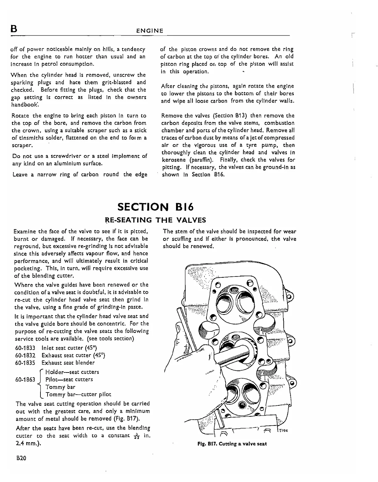
cutting operation should be carried
out
with
the
greatest care, and only a minimum
amount
of
metal should be removed (Fig. B17).
After
the
seats have been re-cut, use
the
blending
cUtter
to
the
seat width
to
a constant
:;JJ
z
in.
2.4
mm.).
B20
The
stem
of
the
valve should be inspected
for
wear
or
scuffing and
If
either
is
pronounced,
the
valve
should
be renewed.
--=--
t-''''---r----.,
I'
A
Fig.
B17.
Cutting a valve seat