ENGINE
B
---------------------
SECTION
82
REMOVING
AND
REPLACING
ROCKER
BOXES
Open
the
twlnseat
and
remove
the
screw
securing
the
left side panel, and
withdraw
It from
two
locating pegs on
the
rear
frame. Disconnect
the
fuse from
the
negative lead from
the
battery,turn
both fuel taps
off,
and
remove
the
fuel
tank
(Section
E1).
Take off
the
ground
(earth)
leadS' from
the
extended
studs and
then
the
tachometer
cable
retaining loop. Remove
the
domed
nutS" securing
the
rocker
feed pipes.
Withdraw
the
feed pipes
from both
rocker
spindles, and retain -
the
four
copper
washers. If these
are
to
be used again,
they
should first be annealed by heating
to
a dull red
color and plunged Into cold
water.
[)Jsconnect
the
three
high tension leads, and
to
avcl1d
possible
damage
at
a later stage
remove
all
three
sparking
plugs.
Remove four bolts and plain washers, n-om each
rocker
box
inspection cover, and
withdraw
both
covers.
If
any difficulty
is
experienced
light taps
from a hide faced mallet
should
effectively
remove
these covers. Remove three socket
head
screws
from inside each
rocker
box, followed by
the
end
bolts (outside). Unscrew
the
eight
rocker
box
bolts
starting
from
the
centre,
noting
their
positions
because
of
their
varying
lengths
(including
the
extended
studs) and
11ft
both
rocker
boxes
away
from
the
cylinder head. Remove
the
six push rods
and four push rod cover
tubes
toget""r
with
their
bottom
cu
ps
and
seals.
Keep careful
note
of
the
location of each push rod,
which must be replaced
in
the
same position
as
when
removed.
Remove
the
securing bolts
in
the
rever~e
order
to
that
shown
in
Fig.
B12,
I.e. slacken
the
highest
number
first.
When
refitting,
ensure
that
the
Joint surfaces
of
both
the
rocker
boxes and cylinder head
are
clean.
lightly grease
the
new
rocker
box
gaskets, and
position
these
on
the
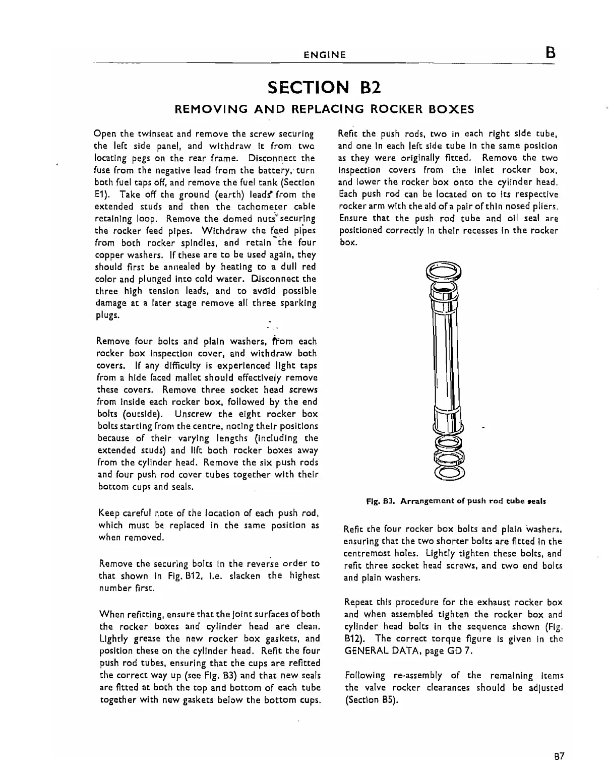
cylinder head. Refit
the
four
push rod tubes, ensuring
that
the
cups
are
refitted
the
correct
way up (see Fig.
B3)
and
that
new
seals
are
fitted
at
both
the
top
and
bottom
of
each
tube
together
with new gaskets
below
the
bottom
cups.
Refit
the
push rods,
two
in
each
right
side tube,
and
one
In
each left side cube
in
the
same position
as
they
were
originally fitted. Remove
the
two
inspection
covers
from the inlet rocker box,
and
lower
the
rocker
box
onto
the
cylinder head.
Each
push rod can be located on
to
Its respective
rocker
arm with
the
aid
of
apalr
of
thin
nosed pliers.
Ensure
that
the
push
rod
tube
and all seal are
pOSitioned correctly
In
their
recesses
In
the
rocker
box.
Fig.
63.
Arrangement
of
push
rod
tube
seals
Refit
the
four rocker
box
bolts
and
plain washers.
ensuring
that
the
two
shorter
bolts
are
fitted
In
the
centremost
holes.
lightly
tighten
these
bolts, and
refit three socket
head
screws, and
two
end bolts
and plain washers.
Repeat this
procedure
for
the
exhaust
rocker
box
and when assembled
tighten
the
rocker
box and
cylinder head bolts
in
the
sequence
shown
(Fig.
B12).
The
correct
torque
figure
is
given
In
the
GENERAL DATA, page GD 7.
Following re-assembly
of
the
remaining items
the
valve
rocker
clearances should
be
adjusted
(Section
B5).
B7