ENGINE
B
------------------
SECTION
B5
ADJUSTING
THE
VALVE
ROCKER
CLEARA~CES
The valve
rocker
clearances should be checked and
If
necessary, adjusted
every
3,000 miles (5,000 Km),
The
correct
clearance for
the
type
of
camshaft
employed, ensures
that
a high valve operating
efficiency
Is
maintained, and
that
the
valves attain
their
maximum useful life.
NOTE:
Adjustment
should
only
be
":lade
when
the
engine
is
cold.
Access
to
'the
rocker
arm
adjuster
screws and lock-
ri~'ts
is
obtained
by
removing
both
the
Inlet and
exhaust rocker Inspection covers. These are
retained
by
four bolts and plain washers.
Adjustment
Is
carried
OUt
with a ring spanners (.5"
AF)
and an open end
spanner
(.25" AF).
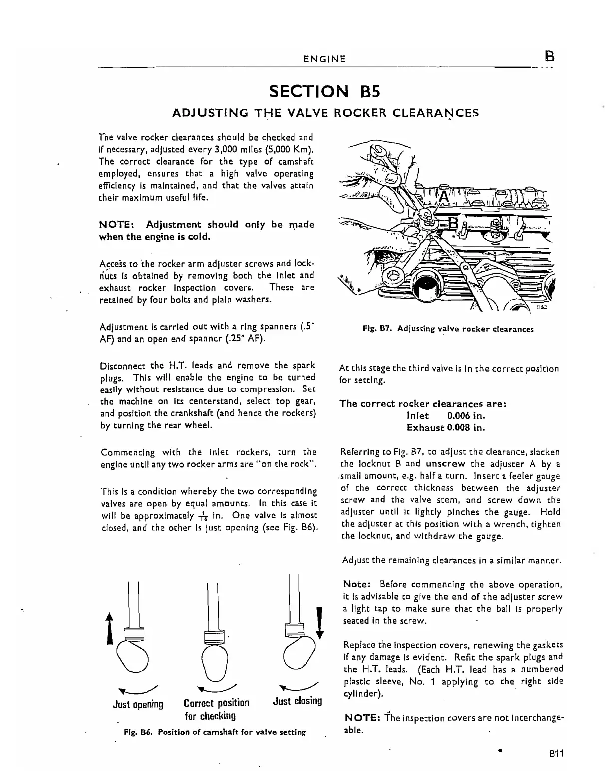
Fig.
87.
Adjusting
valve
rocker
clearances
Disconnect
the
H.T. leads and remove
the
spark
plugs. This will enable
the
engine
to
be
turned
easily
without
resistance
due
to
compression.
Set
the
machine on Its
centerstand,
select
top
gear,
and position
the
crankshaft (and hence
the
rockers)
by
turning
the
rear
wheel.
At
this stage
the
third valve
Is
in
the
correct
position
for setting.
The
correct
rocker
clearances
are:
Inlet
0.006
in.
Exhaust
0.008
in.
Commencing with
the
inlet
rockers,
turn
the
engine
until
any
two rocker
arms
are "on the rock",
This
Is
a condition
whereby
the
two
corresponding
valves are open
by
equal amounts.
In
this
case
it
will be approximately
+.
in.
One
valve
is
almost
closed. and
the
other
is
just
opening (see
Fig.
Bb).
Referring to
Fig.
B7,
to
adjust
the
clearance, slacken
the
locknut B and
unscrew
the
adjuster
A
by
a
small amount, e.g. half a
turn.
Insert
a feeler gauge
of the correct thickness
between
the adjuster
screw
and
the
....
alve
stem,
and
screw
down
th:!
adjuster until It lightly pinches
the
gauge. Hold
the
adjuster at this
position
with
a
wrench,
tighten
the
locknut, and
withdraw
the
gauge,
Adjust the remaining clearances
In
a,similar manner.
Fig.
86.
Position
of
camshaft
for
valve
setting
NOTE:
The inspection
covers
are
not
interthange-
able.
Replace the inspection covers,
renewing
the
gaskets
If
any damage
Is
evident.
Refit
the
spark
plugs and
the
H.T. leads. (Each H.T. lead has a
numbered
plastic sleeve, No. 1 applying
to
the
right side
~Iinde~.
.
Note:
Before commencing the above operation,
it
is
advisable
to
give
the
end
of
the
adjuster
screw
a light tap
to
make
sure
that
the
ball
Is
properly
seated
In
the screw.
~
Just
closing
~
Correct
position
for
checlling
~
Just
opening
t
•
B11