B
ENGINE
Either camshaft
can
be
advanced or retarded
In
steps
of
15 degrees. which
Is
equal
to
one
tooth
on
the
camshaft
pinion.
or
5 degrees
by
assembiing
the
pinion on a different keyway.
Re-assembly notes
are
given
in
5ectlon
B29.
The
Ignition timing
procedure
is
fully described
in
Section
B26.
NOTE
When
checking
the
valve timing
after
assembly, due to the intermediate wheel having a
prime number of teeth, the timing
marks
will only
coincide every 94th revolution,
thus
there
Is
no
cause for alarm ifche marks will not readily re-allgn.
SECTION
831
TO
DISMANTLE
AND
REASSEMBLE
THE
CRANKCASE
(1) Remove
the
engine unit (Section
B1).
(2) Remove
the
rocker
boxes (Section
B2).
(3) Remove
the
carburetors
(Section
B8).
(4) Remove
the
cylinder head (Section 812).
(5) Remove
the
cylinder block (Section 817).
DO
NOT
FORGET
TO
PROTECT
THE
CONNECTING
RODS
FROM
DAMAGE.
(6) Remove
the
pistons (Section 820).
(7)
Remove
the
primary chain, engine
sprocket.
shock
absorber.
and gearshift crass-shaft.
(Section
C5-Cl).
(8) Remove
the
clutch and housing (Section C7).
(9) Remove
the
oil pump (Section A7).
(10) Remove
the
transmission (gearbox)
outer
cover (Section D2).
(11) Remove
the
transmission (gearbox) Inner
cover and
gear
cluster (Section D7).
(12) Remove
the
timing
cover
(Section
B28).
(13) Remove
the
rotar
and
stator.
To
remove
the
right side crankcase section
It
is
nOt necessary
to
remove the timing pinion
and
distance
piece.
If
for any reason
the
pinion
Is
removed,
note
that
this
Is
keyed
to
the
crankshaft
and
will need
the
use
of
an
extractor.
The
Intermediate
timing gear
with
Its retaining
circlip
and
thrustwasher must be removed next.
For valve timing purposes on re·assembly, refer
to
Section
B30.
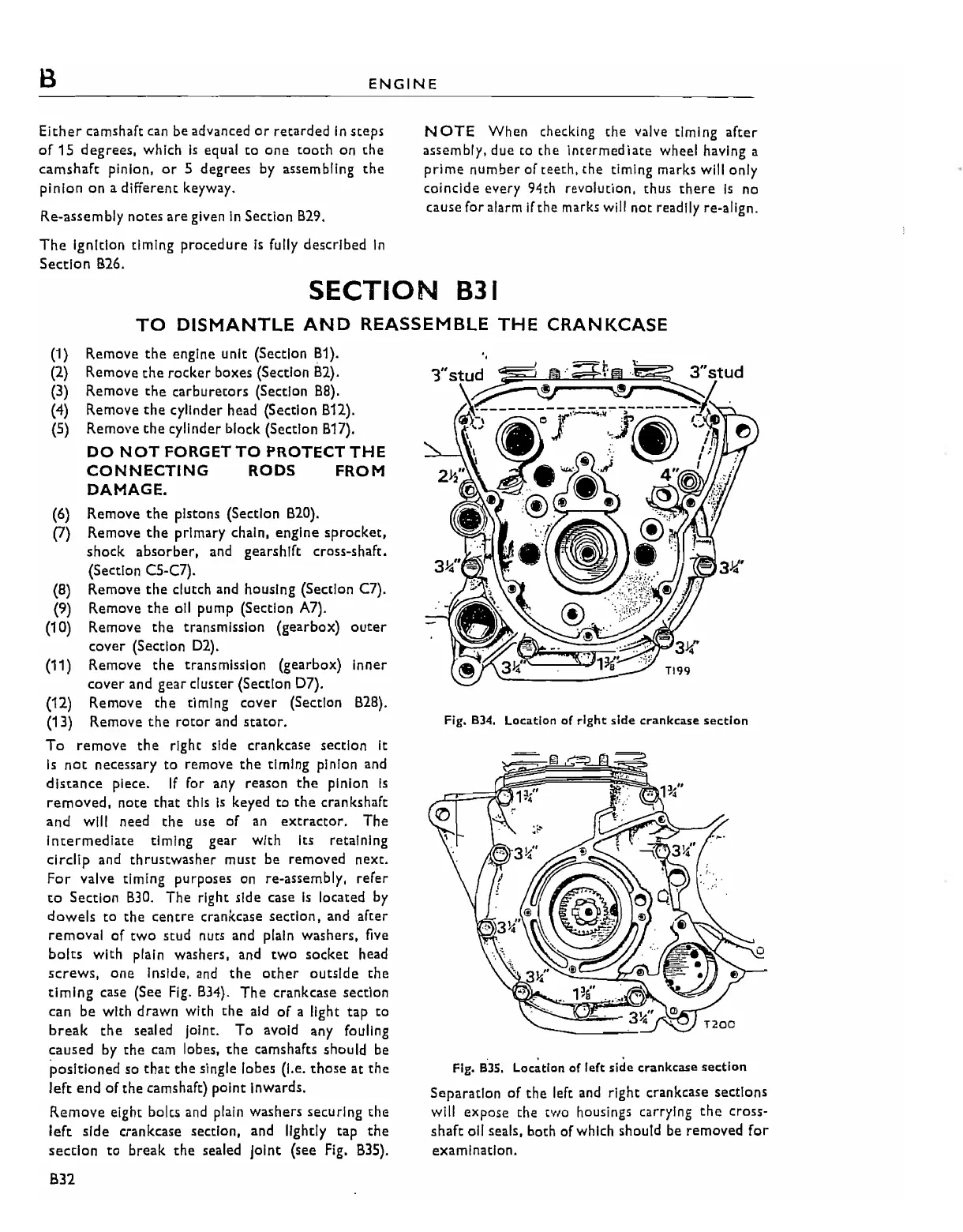
The right side case
Is
located
by
dowels
to
the
centre
crankcase
section,
and after
removal
of
two
scud
nuts
and
plain
washers, five
bolts
with plain washers. and
twO
socket
head
screws,
one
Inside,
and
the
other
outside
the
timing
case (See
Fig.
B34).
The
crankcase section
can be with drawn with
the
aid
of
a light
tap
to
break
the
sealed joint. To avoid any fouling
caused
by
the
cam lobes,
the
camshafts should be
positioned
so
that
the
single lobes (I.e.
those
at
the
left
end
of
the camshaft) point Inwards.
Remove
eight bolts and plain washers securing
the
left
side crankcase section, and lightly tap
the
section
to
break
the
sealed Joint (see
Fig.
835).
B32
Fig. 834. Location
of
right
side
crankcase
section
Fig.
BJS.
Loc~t1on
of
left
side
crankcase
section
Separation
of
the
left and right crankcase sections
will
expose
the two housings carrying the cross-
shaft
011
seals. both of which should be removed
for
examination.