ENGINE
SECTION
B4
STRIPPING
AND
REASSEMBLING
THE
ROCKER
BOXES
B
Removal of
the
rocker
spindles
from
the
rocker
boxes
Is
best achieved by
driving
them
out,
using a
soft metal drift.
When
the
spindles
are
removed,
the
rocker arms and
washers
can
be
withdrawn.
All
parts should
be
thoroughly
cleaned
in
kerosene,
(paraffin), and
the
oliways
In
the
spindles should be
cleaned with a
jet
of
compressed
air.
Remove
the
'0'
rings
from
the
rocker
splndle~
and
renew them.
If
It
Is
required
to
renew
the
rocker
ball pins,
the
old ones should
be
removed
by means
of
a suitable
drift. New ones should
then
be
pressed In.
To ensu re
an
oli-tlght seal
between
the
rocker
box
and cylinder head,
In
cases
where
an oli leak
cannot
be cured
by
fitting
new
gaskets,
the
Joint surface
of
the
rocker
box
should
be
IInlshed
to
remove
any
Irregularities.
An
effective finish can
be
achieved by lightly rubbing
the
junction surface
on
a
sheet
of
emery
cloth
mounted on a truly flat surface (such as a piece of
plate glass).
The following method
of
assembly
Incorporates
the
use
of a home made
alignment
bar. which can be
made from a
-{-;
In.
dla.
bar
X
9-!-
In. long
by
grinding
a taper at one end.
Smear
the
plain washers
with
grease
and place
them against the cast bosses or rocker arms
as
shown
In
Fig.
BS.
Commencing from
the
left end
of
each
rocker
box
(I.e. end with larger hole), fit
the
rocker
arms.
Compress each Thackery
washer
(double-coli) with
thin nosed pliers and assemble
these.
Align each
rocker
In
turn
with
the
alignment
bar.
When
all
the
arms and washers
are
correctly
aligned, remove
the
bar.
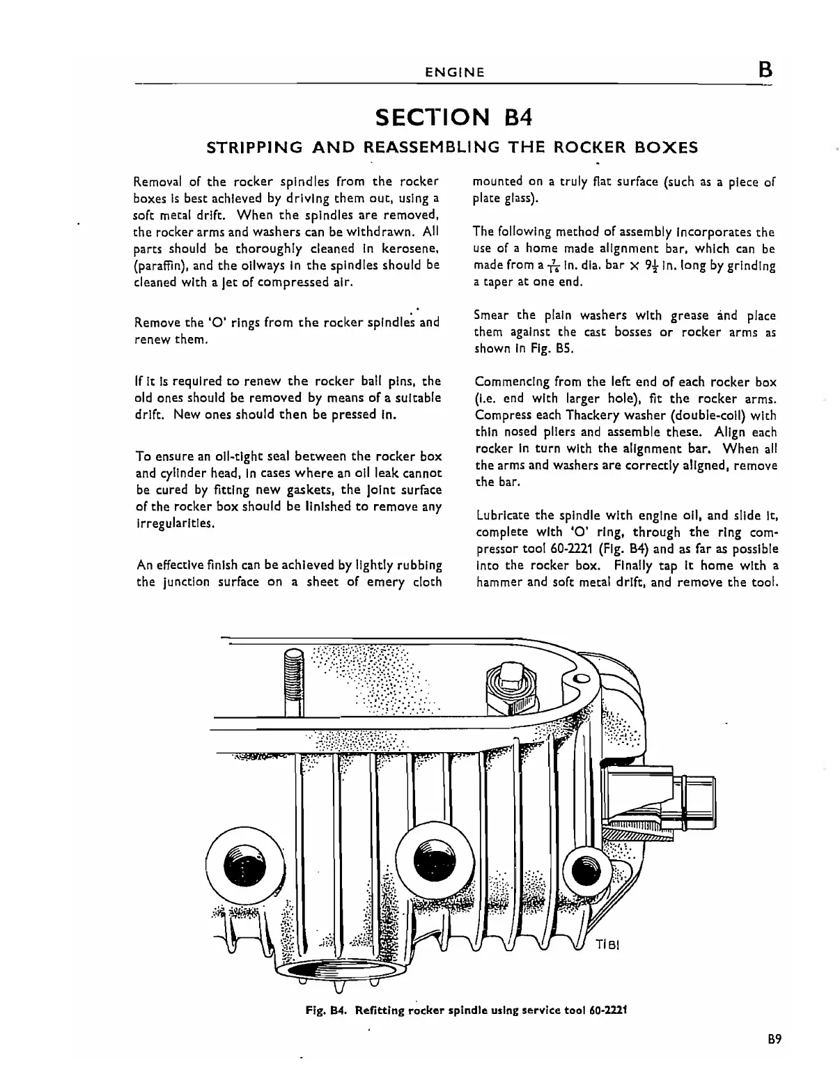
Lubricate
the
spindle
with
engine oil, and slide it,
complete with
'0'
ring,
through
the
ring com-
pressor
tool
60-2221
(Fig.
B4)
and as far as possible
Into
the
rocker
box. Finally
tap
It
home
with
a
hammer and soft metal drift, and
remove
the
tool.
Fig. 84. Refitting rocker spindle using service tool
60-2221
B9